
An Endpoint runs no BlastShield software. It sits behind a BlastShield Gateway, and the Gateway does the work. When one Endpoint talks to an Endpoint behind a different Gateway, the two Gateways connect out to the Orchestrator, which introduces them to each other. They then build an encrypted tunnel directly between themselves. This article explains each step, the firewall rules involved, and what happens when a NAT or firewall prevents the direct tunnel.
Applies to: BlastShield Orchestrator 1.14.4
Connection diagram
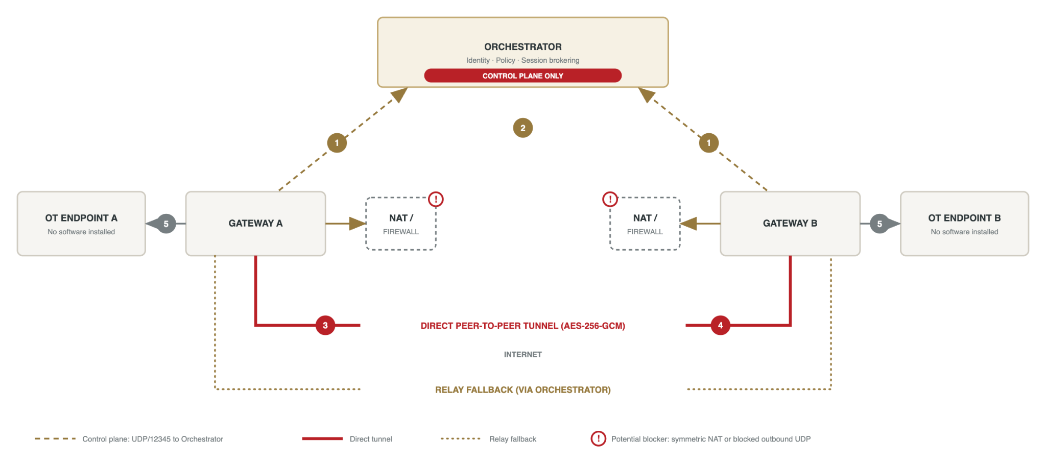
The numbers in the diagram match the steps below. The red exclamation marks show where a symmetric NAT or blocked outbound UDP can stop the direct tunnel.
Before you begin
-
Each Gateway needs outbound UDP to the Orchestrator on port 12345.
-
Each Gateway also needs outbound UDP to the other Gateway. The ports are set by each NAT device and cannot be limited to a single number.
-
No inbound firewall rules are needed at either site. Neither Gateway accepts connections.
-
Policy must allow the two Endpoints to communicate. An Endpoint can reach only the BlastShield nodes it is authorized to reach.
-
Each Endpoint has an address inside the BlastShield network. That address is invisible to the underlay network.
How the connection works
Step 1. Outbound registration. Each Gateway sends outbound UDP to the Orchestrator on port 12345. Each site's NAT creates a mapping and translates the source port. The Orchestrator records the resulting public address of each Gateway.
Step 2. Session brokering. Each Gateway authenticates with its own ECDSA key. The Orchestrator gives each Gateway the other's public key and public address, then leaves the path. It never carries the session.
Step 3. Simultaneous hole punch. Both Gateways send packets directly to the address they received, at the same time, from the same sockets they used to reach the Orchestrator. Each outbound packet makes its own NAT accept the reply from the other Gateway, so the connection is treated as direct.
Step 4. Direct encrypted tunnel. The Gateways run an ECDHE key exchange over the established path, authenticated by their ECDSA identities. HKDF derives the AES-256-GCM session keys. All traffic between the Gateways is encrypted and integrity-protected.
Step 5. Delivery to the Endpoints. Endpoint A sends ordinary IP traffic to the BlastShield address of Endpoint B. Gateway A carries it through the tunnel. Gateway B ends the tunnel, applies policy and forwards the traffic to Endpoint B. Return traffic uses the same tunnel in the opposite direction.
From step 1 onward all communication between the Gateways and the Orchestrator is UDP. No new ports are assigned. The tunnel reuses the NAT mappings created in step 1. The tunnel runs between the Gateways. The link between each Endpoint and its Gateway is the local network.
Endpoints behind the same Gateway
Two Endpoints behind one Gateway do not need a tunnel. In MAC and VLAN addressing modes all Endpoint traffic passes through the Gateway, including traffic between local Endpoints. Packets that policy does not allow are dropped and their connections reset.
Addressing modes and who can start the conversation
-
Source+Destination NAT. Endpoints cannot initiate connections over the overlay. They can only receive them.
-
Destination NAT. Endpoints can initiate connections over the overlay. The Gateway's Endpoint interface must be the Endpoint's default gateway, or the Endpoint needs a static route to the overlay prefix.
-
MAC and VLAN. Endpoints are reachable only through the overlay and all traffic passes through the Gateway.
When the direct path fails
The hole punch works only if each Gateway presents one stable public port to every destination. Two conditions break this:
-
Symmetric NAT. The NAT assigns a different public port for each destination. The address the Orchestrator gave the other Gateway is then wrong, so the step 3 packets hit a closed port. This acts like a UDP block at steps 3 and 4.
-
Blocked UDP at step 3 or 4. A firewall drops UDP between the Gateways, so the hole punch (step 3) or the tunnel traffic (step 4) never arrives.
With two sites there are two NATs and two firewalls that can cause this. Either site can break the direct path.
When the direct path fails, the session falls back to relaying. The Orchestrator forwards packets between the Gateways. The session keeps working, but traffic takes a longer route and adds latency.
Confidentiality is preserved while relaying. The payload is encrypted with the peer-to-peer key before it is relayed. The Orchestrator decrypts only the outer layer it needs for forwarding.
Check whether a session is relayed
A peer moves through SendingConnect and KeyVerification before it reaches Connected. A short period in Relaying before Connected is normal. A session that stays in Relaying means UDP is blocked at step 3 and/or step 4.
Fix a relayed session
-
Allow outbound UDP from both Gateways to all BlastShield peers. Do not limit it to a destination port.
-
Make sure each site's NAT presents one public port per source. This is often called endpoint-independent mapping or cone NAT. Disable symmetric or port-randomizing NAT for BlastShield traffic.
-
If the device cannot do this, exempt BlastShield UDP from the NAT or firewall policy that randomizes ports, using a rule scoped to the Gateways.
-
Confirm both Gateways reach Connected and stay there.
|
Note |
|---|
|
If the direct path cannot be allowed, relaying remains a working fallback. |