Hyper-V Gateway installation
This article explains how to install the BlastShield™ Gateway vhdx in Hyper-V.
A Gateway deployed in Hyper-V can be configured to support any of the following addressing modes:
Source+Destination NAT
Destination NAT
MAC Address
VLAN
Gateway addressing modes are explained in more detail here: Gateway Addressing Modes
Gateway use cases are described here: Gateway types and their use cases
A Hyper-V hypervisor with admin access.
A BlastShield™ Orchestrator with administrator access.
The hardware requires a minimum of one physical NIC for a passive Gateway deployment or at least two physical NICs for an inline Gateway deployment.
Outbound UDP ports to all required destinations.
Resolution of DNS requests must be supported by the network.
Download the Gateway vhdx file from here and keep it available so that you can upload it to your hypervisor.
You will need the vhdx file which you downloaded in the previous step.
Open the Hyper-V Manager.
From the Action Pane, click New, and then click Virtual Machine.
From the New Virtual Machine Wizard, click Next.
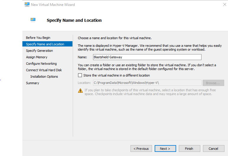
Choose a name for the virtual machine and a location. The default location is fine. Click Next.
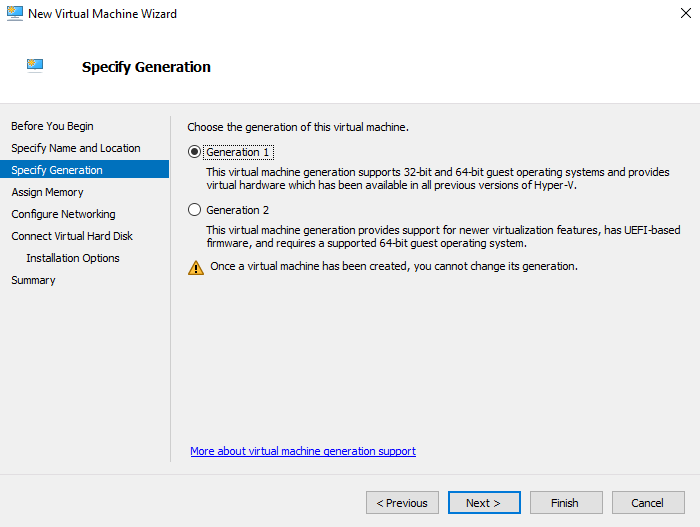
Select Generation 1 as the generation for the virtual machine and click Next.
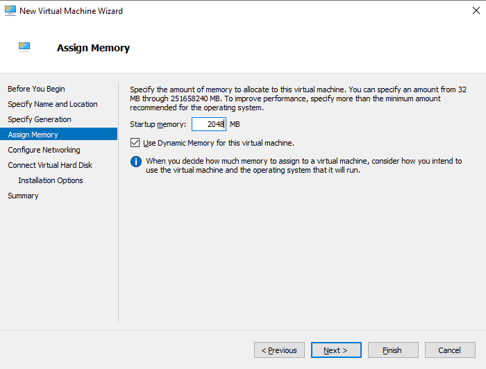
Select 2GB as the startup memory and click Next.
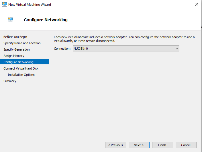
Select the upstream interface for the Gateway as the network adapter. This interface should have access to the Orchestrator. If you will also use a downstream interface, then you can add this later. Click Next.
Select the BlastShield™ Gateway vhdx file as the virtual hard disk and click Next.
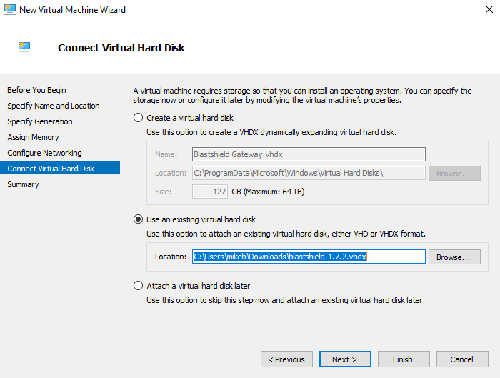
Verify your choices in the Summary page and then click Finish.
In Hyper-V Manager, right-click the virtual machine and select connect.
In the virtual machine connection window, select Action > Start.
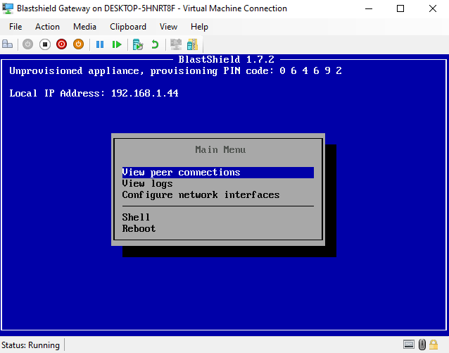
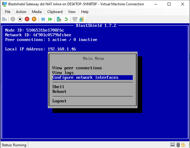
When the Gateway has booted up, you will see the Gateway console menu. Make a note of the Provisioning PIN code and Local IP Address which you will need when you provision the Gateway in the Orchestrator.
If you are configuring an Inline Gateway, which requires separate Uplink and Endpoint ethernet interfaces, then add a downstream interface to the virtual machine. You can skip this step if you are using a source+destination NAT passive Gateway.
In the Hyper-V Manager go to the Virtual Machines pane.
Right-click on the virtual machine and select Shut Down to turn it off.
Right-click on the virtual machine again and select Settings.
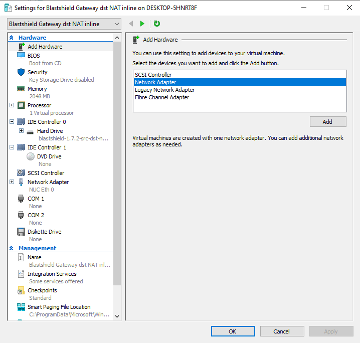
In the Settings pane, go to Add Hardware, and select Network Adapter, then click on Add.
In the Network Adapter pane, choose the Virtual Switch that corresponds to the endpoint interface on the appliance.
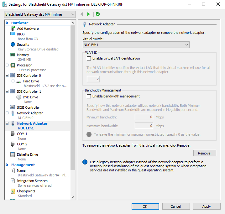
Click on OK and Apply.
Open the Hyper-V Manager.
In the virtual machine connection window, verify that the VM is running. If not, then select Action > Start.
In Hyper-V Manager, right-click the virtual machine and select connect.
You will see the Gateway console menu. Login with your console password. The console password is set in the Orchestrator.
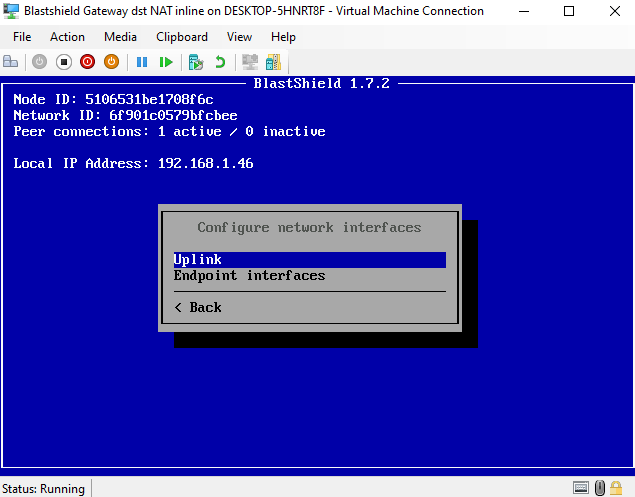
Chose Configure network interfaces.
To configure the uplink interface, choose Uplink.
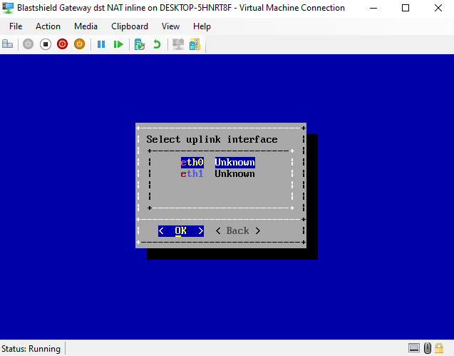
Select the uplink interface from the list. Use the up/down arrow keys to select it and press OK.
Select the Address Configuration mode to DHCP or Manual Configuration. If you are using manual configuration, set the IP Address, Default Gateway and DNS IP Addresses.
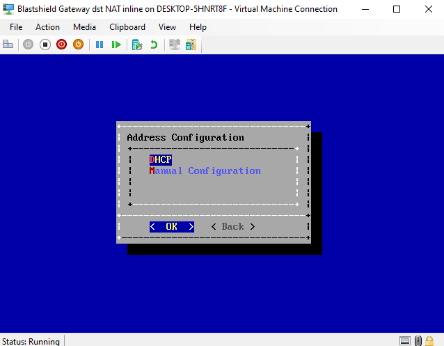
Hit OK to save the configration and return to the Configure Interfaces menu.
For Inline Gateways, you must configure at least one endpoint interface. To do this, select the Endpoint Interfaces option and hit enter.
Select the endpoint interface(s) from the list using the space bar.
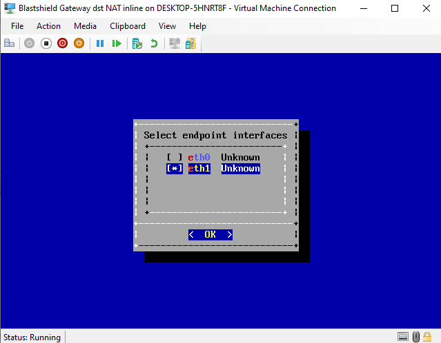
Hit OK to save the configuration and return to the Configure Interfaces menu.
The IP address of the endpoint interface is provisioned in the Orchestrator, in the Gateway configuration.
From the Orchestrator, select "Gateways" from the left Menu.
Select "Add New Gateway" from the Gateway List.
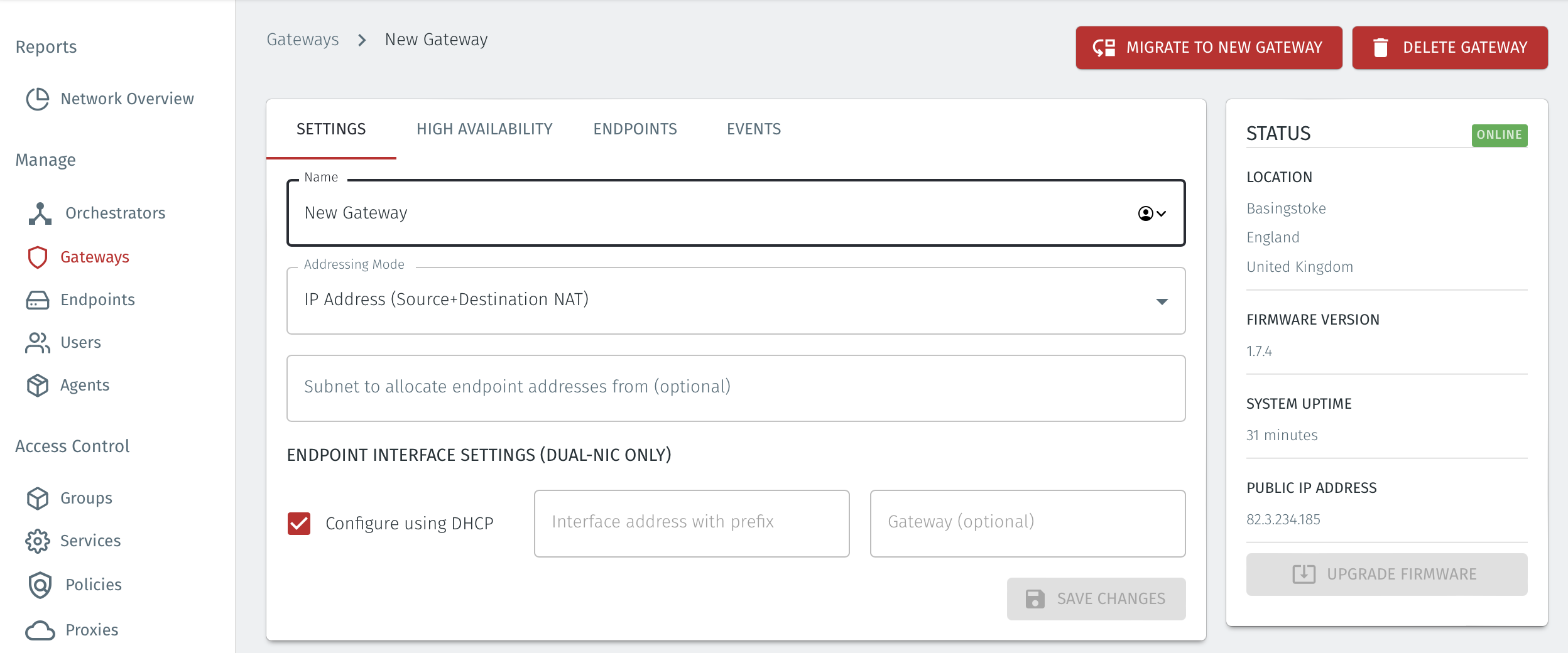
Enter a Name for the new Gateway.
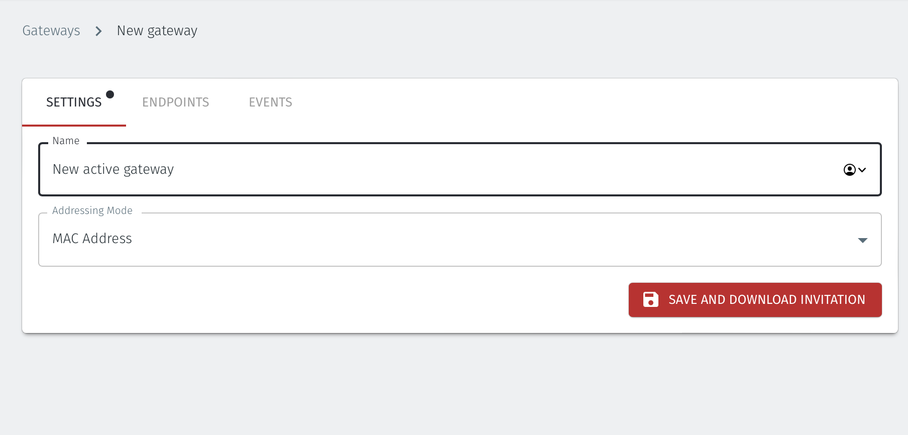
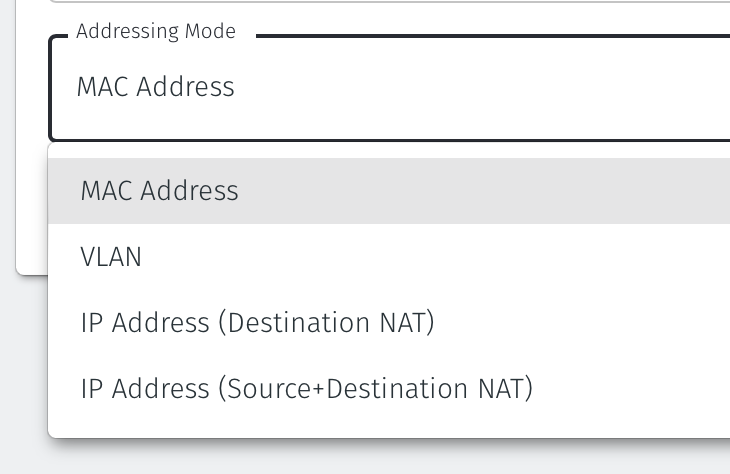
Set the Addressing Mode for the Gateway. Choose from the following options:
For MAC Addressing mode, click on MAC Address as the Addressing Mode.
For VLAN adressing mode, click on VLAN.
For Destination NAT addressing mode, click on IP Address (Destination NAT).
For Source and Destination NAT addressing mode, click on IP Address (Source+Destination NAT).
Endpoint Interface Settings.
The following steps apply only to Gateways using NAT addressing modes.
If you are using the Gateway in a single NIC configuration, leave the Endpoint Interface Settings as default.
If you are using the Gateway in a dual NIC configuration, then configure the Endpoint Interface Settings:
If you want the endpoint interface to get it's IP address via DHCP, then leave the configure using DHCP box checked.
If you want to manually set the endpoint interface IP address , then un-check the configure using DHCP box.
Set the Interface address with prefix field to the same IP address as the router which the Gateway is replacing. Use CIDR format.
If you will be onboarding endpoints which are not within the subnet you specified with the interface address above, then enter the IP address of the gateway required to reach the endpoints in the Gateway (optional) field.
If you do not have a route on your internet router to the protected endpoint network, then enable NAT external connections by checking the box.
To enable the Gateway to forward non-endpoint connections from the protected network to the public side of the Gateway, check the Forward connections for non-endpoint addresses box. This will allow devices which are situated on the protected network side of the Gateway, which are not provisioned as endpoints on the Gateway, to forward traffic out through the Gateway.
Leave the Subnet to allocate endpoint addresses from blank if you want the system to allocate the overlay IP address (default). If you want to specify the subnet, then enter it here in CIDR format.
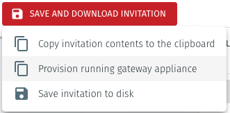
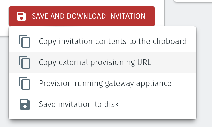
Click on Save and Download Invitation.
There are two options for registering the Gateway. You can use the Provision running gateway appliance if you have access to the Orchestrator, or use the External provisioning URL method if someone without Orchestrator access is going to provision the Gateway.
Option1:Provision running gateway appliance method
To use the Provision running gateway appliance method watch the following video or read the steps below. You will require port 80 connectivity to the Gateway and be logged onto the Orchestrator:
Click on the option Provision running gateway appliance to start the Gateway provisioning process.
The Provision Gateway window will open. Use the provisioning PIN code and Local IP Address that is displayed on the Gateway console menu.
IP Address of Gateway: enter the IP address of the Gateway that is displayed in the Gateway console menu.
Provisioning PIN code: enter the provisioning PIN code that is displayed in the Gateway console menu.
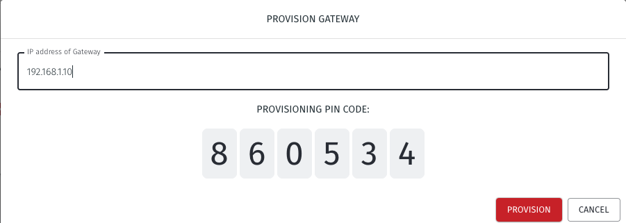
Click the Provision button to continue.
When the Gateway provisioning has completed, the Registration successful message will be displayed.
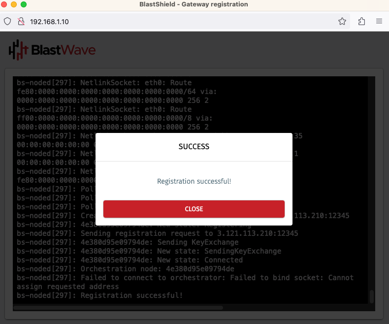
The Gateway status in the Orchestrator will show Online.
Option 2: The External provisioning URL method
To use the External provisioning URL method, watch the following video or read the steps below. Your workstation will need port 80 access to the Gateway but it does not require Orchestrator access:
Click on the option Copy external provisioning URL.
Open the provisioning URL in a browser.
Enter the Gateway IP address and the provisioning PIN from the Gateway console menu.
Click on Register.
A new Gateway Provisioning browser window will open.
When the registration is complete, the Gateway provisioning browser window will display Registration Successful.
You can now close the browser window and verify that the Gateway is online in the Orchestrator.
From within the Orchestrator, select "Gateways" from the left Menu
Select the desired Gateway from the Gateway List
Select "Add New Endpoint"
Enter a name for the new endpoint
Check "Endpoint Enabled" to Enable it when done.
The IP address is auto-populated.
Configure the endpoint Destination field.
If the Gateway is using either of the NAT addressing modes, enter the endpoint's private IPv4 LAN address or hostname.
If the Gateway is using MAC address addressing mode, enter the endpoint's MAC Address.
If the Gateway is using VLAN addressing mode, enter the endpoint's VLAN ID.
For a Gateway using Destination NAT addressing mode, If you want the endpoint to be able to communicate out through the Gateway then check the box marked Allow outbound external network connectivity.
Click on Save Changes to confirm.
If the endpoint is reachable from the Gateway the the status of the endpoint will show as ONLINE.
If it does not show as online, then check the connectivity between the Gateway and the endpoint device.
For endpoints on Gateways which use destination NAT addressing mode only, modify the endpoint's route table so that the endpoint may connect out over the BlastShield™ network. If you are using a Gateway which is set to Source + Destination NAT you can skip this step.
Provision the Gateway endpoint interface address as the default gateway on the endpoint, or provision it as a static route to the BlastShield™ overlay network prefix.
The BlastShield™ overlay network prefix is shown in the network settings/Overlay Subnet settings in the Orchestrator.
You can find the Gateway endpoint interface address from the Orchestrator in the Gateway settings, under Endpoint Interface settings (Dual NIC only) > Interface address with prefix.
About Groups
Groups allow you to micro-segment users and endpoints. A group is a logical collection of endpoints and/or users that are grouped together. Groups are connected via policies, which form the foundation for BlastShield access control and segmentation management.
Any combination of endpoints and/or users can be grouped together.
There is no limit to the number of endpoints and/or users that can be in a group.
Endpoints and users can be in one or multiple groups simultaneously.
Groups are linked together via policies to provide access between endpoints.
By default, endpoints/users cannot access or have visibility to other endpoints/users unless they are granted access via a policy
About Policies
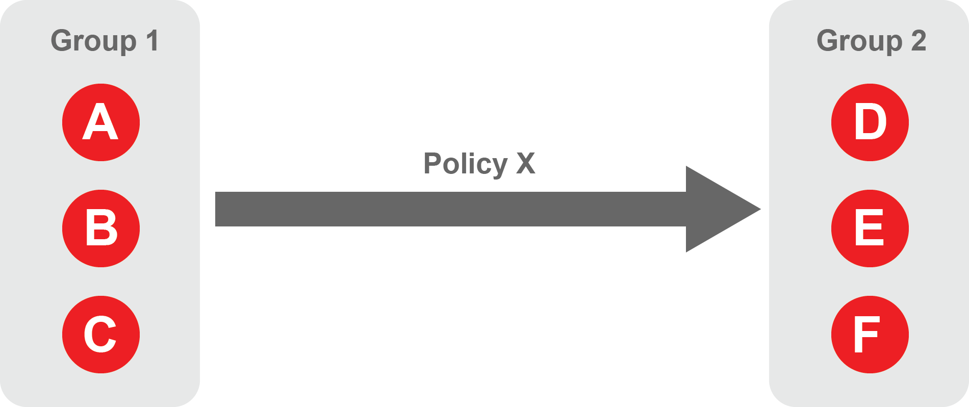
A policy defines how groups can interact. Groups are connected via policies, which form the foundation for BlastShield access control and segmentation management.
Each policy will have two sets of groups - "From" and "To".
The "From" set is one or more source groups.
The "To" set is one or more destination groups.
There is no limit to the number of groups in a given policy.
"From" Groups will have access to "To" Groups within the policy.
"To" Groups will not have access to "From" Groups within the policy.
Groups can be in one or multiple policies simultaneously.
 |
Create Groups
From the Orchestrator, select "Groups" from the left menu.
Select "Add New Group" from the Group List.
Enter a name for the new Group.
To add members to the new group, click the "Add Members" button.
If you adding users to the group then select the desired Users which you want to be associated with the Group from the "Users" box.
If you are adding Agents to the group then select the desired Agents which you want to be associated with the Group from the "Agents" box.
If you are adding Gateway Endpoints then select the desired Endpoints from the "Endpoints" box.
Alternatively, you can leave the members list empty and add/modify new members later.
Click "Add Members" to save the members.
Click "Save" to save the new group.
Repeat, if required, to ensure you have one group for your endpoints and one group for your users, which is the minimum you will need in order to define the access policy.
Please refer to the following video, which is an example of creating one group for your users and one group for Host Agents.
Create a Policy to link your Groups
Note
Users and Agents must be a member of a group for them to be used in a policy.
Select "Policies" from the left menu.
Select "Add New Policy" from the Policy List.
Enter a name for the new Policy.
Select desired "From" Groups to be associated with the new Policy.
Select desired "To" Groups to be associated with the new Policy.
Save the new Policy.
Policies are directional, so that you can control the direction in which connections may be initiated. Typically for remote access use-cases your policy would be from the "user group" to the "server group" so that users may start connections to the servers, but servers cannot start connections to users. You can create bi-directional permissions by using two policies.
The following video shows an example of creating an access Policy between a group of remote workers and a group of servers. The policy gives the remote workers authorisation to access the server group.