Running a Gateway as a container in NAT mode
The BlastShield Gateway supports running as a container. The image will run on 32-bit arm, 64-bit arm and x86_64. The Gateway addressing mode must use either source+destination NAT or destination NAT.
Running the Gateway as a container will allow you to use it alongside other apps running in the same environment, allowing for a more cost effective use of hardware platforms.
The following diagram shows a source + destination NAT passive Gateway implemented using a Docker container.
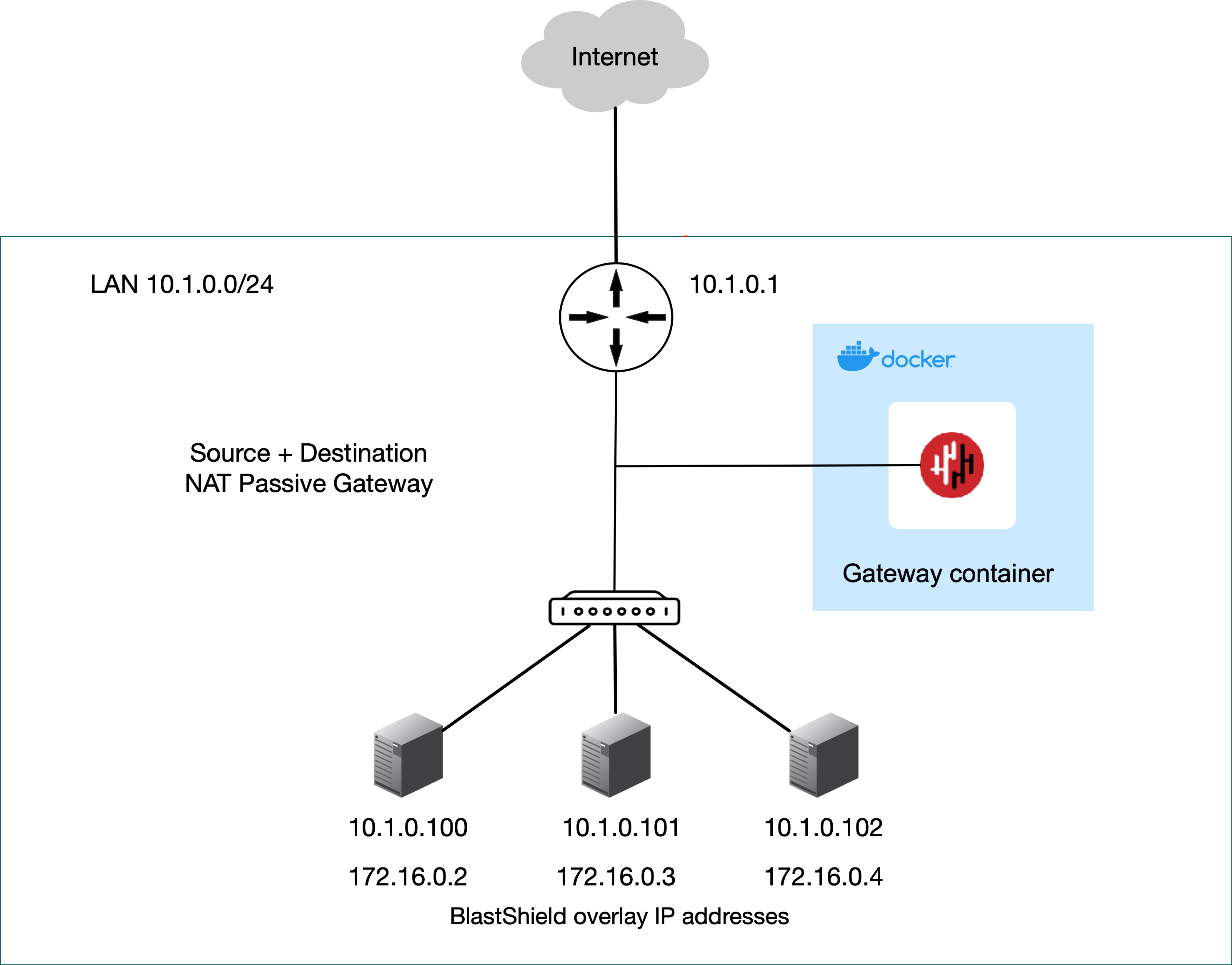 |
The endpoints are able to communicate freely on their local LAN whilst at the same time secure remote access for users over the BlastShield™ network to these endpoints is managed by the Gateway. Endpoints will not be able to initiate connections out over the BlastShield™ network overlay because there is no route to the overlay network (if this is required, then use 'Destination NAT' mode).
The following diagram shows a destination NAT inline Gateway implemented using a Docker container.
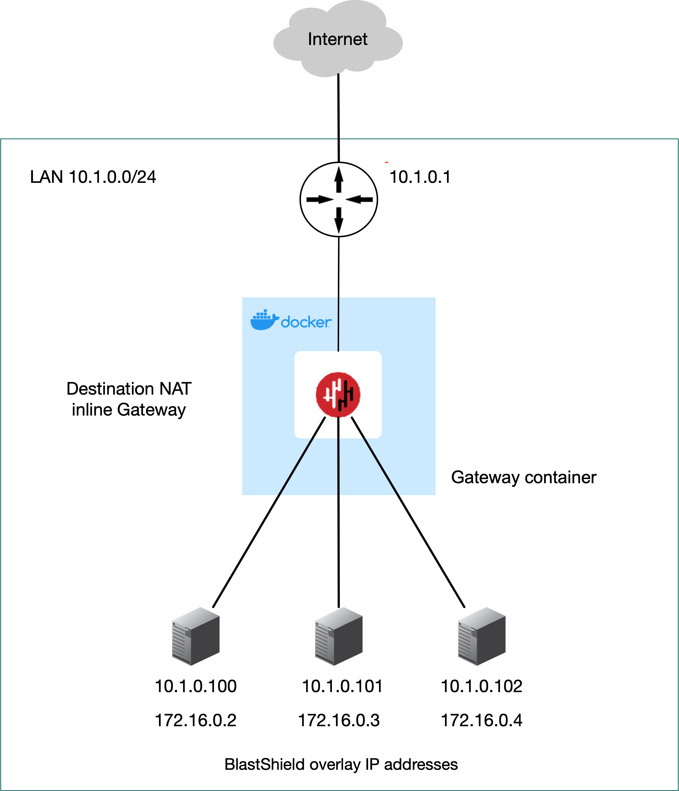 |
The Gateway is located inline in the network path and provides isolation at the network layer, providing a virtual-air gap to protected endpoints so they appear invisible and isolated to unauthorized users. The endpoints are able to communicate freely on their local LAN. Endpoints will be able to initiate connections out over the BlastShield™ network, provided the endpoints have a route added to the BlastShield™ overlay via the Gateway local LAN address.
Prerequisites
A BlastShield™ Orchestrator with administrator access..
An appliance running 32-bit arm, 64-bit arm or x86_64 Linux with at least one physical NIC and a container environment installed.
The BlastShield™ Gateway requires outbound UDP ports to all required destinations.
Outbound UDP ports to all required destinations.
Resolution of DNS requests must be supported by the network.
To learn how to run a BlastShield Gateway as a container and then create endpoints on it, please read the steps below.
Create a new gateway in the orchestrator and set the mode to "Source + destination NAT".
Connect to the Orchestrator and select Gateways from the left Menu.
Select Add New Gateway.
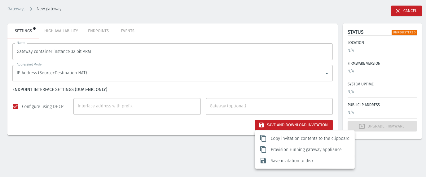
Enter a name for the new Gateway.
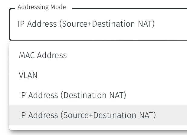
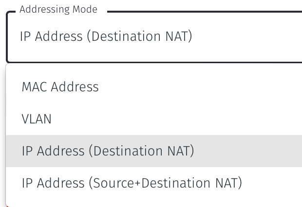
Select Addressing Mode for the Gateway to be IP Address (Source+Destination NAT).
Select Save and Download Invitation and copy it to the clipboard. Keep the invitation data as you will need it in the next step.
Using the template below, create a Docker compose file. Copy this yaml file to a new directory on the appliance.
In the yaml file, set the
imagevariable to use the release you want. The example below uses version 1.7.1.In the yaml file, replace the "REPLACE_ME" value in the with the invitation data which you copied from the Orchestrator.
From that directory, run the command:
docker-compose up.
An example yaml file is given below.
docker-compose.yml
version:  "3.8"
services:
    blastshield-gw:
        image: public.ecr.aws/blastwave/blastshield-gw:1.7.1
        volumes:
            - blastshield-private:/data
        environment:
            INVITATION: 'REPLACE_ME'
        restart: unless-stopped
        cap_add:
            - NET_ADMIN
        sysctls:
            - net.ipv4.ip_local_port_range=16384 32767


volumes:
    blastshield-private:
Create a new gateway in the orchestrator and set the mode to "Source + destination NAT".
Connect to the Orchestrator and select Gateways from the left Menu.
Select Add New Gateway.
Enter a name for the new Gateway.
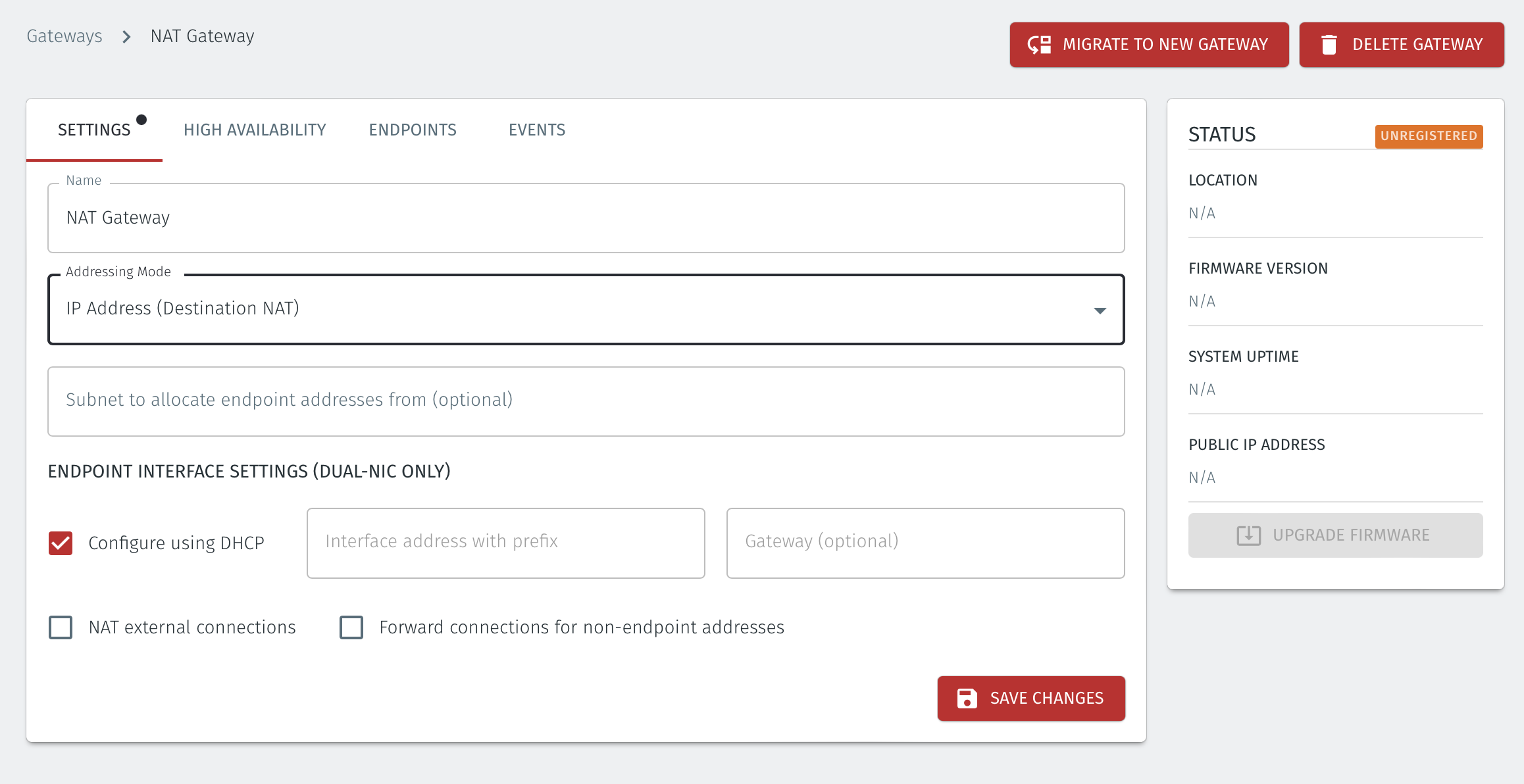
Select Addressing Mode for the Gateway to be IP Address (Destination NAT).
Select Save and Download Invitation and download the invitation file. Keep the invitation data as you will need it later.
If you are using the Gateway in a single NIC configuration, leave the Endpoint Interface Settings as default.
If you are using the Gateway as a in a dual NIC configuration, then configure the Endpoint Interface Settings:
If you want the endpoint interface to get it's IP address via DHCP, then leave the configure using DHCP box checked.
If you want to manually set the endpoint interface IP address , then un-check the configure using DHCP box.
Set the Interface address with prefix field to the same IP address as the router which the Gateway is replacing. Use CIDR format.
If you will be onboarding endpoints which are not within the subnet you specified with the interface address above, then enter the IP address of the gateway required to reach the endpoints in the Gateway (optional) field.
If you do not have a route on your internet router to the protected endpoint network, then enable NAT external connections by checking the box.
To enable the Gateway to forward non-endpoint connections from the protected network to the public side of the Gateway, check the Forward connections for non-endpoint addresses box. This will allow devices which are situated on the protected network side of the Gateway, which are not provisioned as endpoints on the Gateway, to forward traffic out through the Gateway.
Select Save and Download Invitation and copy the invitation contents to clipboard. Keep the invitation data as you will need it later.
Using the template below, create a Docker compose file.
Set the image variable to match the release version you want to use. The example below uses release 1.7.4
Add the invitation text to the compose file as the value of the
INVITATIONvariable to replace where it says "REPLACE_ME".Add the name of the interface on the Gateway appliance which the endpoints can be accessed from as the value of the
ENDPOINT_IFACEvariable.
Copy the Docker compose file to a new directory on the host appliance.
From that directory, run the command:
docker-compose up.
An example yaml file is given below.
docker-compose.yml
version:  "3.8"
services:
    blastshield-gw:
        image: public.ecr.aws/blastwave/blastshield-gw:1.7.4
        volumes:
            - blastshield-private:/data
        environment:
            INVITATION: 'REPLACE_ME'
            ENDPOINT_IFACE: PUT_THE_ENDPOINT_INTERFACE_NAME_HERE
            LEGACY_IPTABLES: 1
        restart: unless-stopped
        cap_add:
            - NET_ADMIN
        network_mode: host


volumes:
    blastshield-private:
For each of the devices that you want to securely access via the BlastShield™ Gateway, you must create a corresponding Endpoint for it on the Gateway.
Follow this procedure to learn how to create an Endpoint on the Gateway.
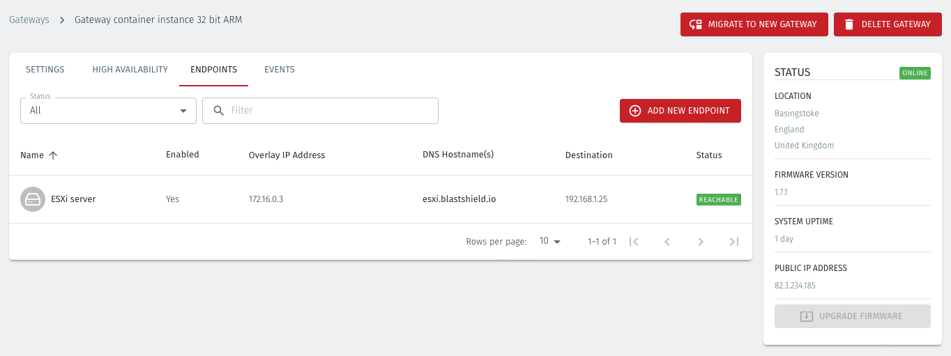
In the Orchestrator, select the Gateway and click on the Endpoints tab.
Click the 'Add New Endpoint' button and click on the 'Endpoint Enabled' button.
Enter a name for the Endpoint in the Name field.
In the DNS Hostname field, enter a hostname.
In the Destination field, enter the device's Private IPv4 address or hostname.
For a Gateway using Destination NAT addressing mode, If you want the endpoint to be able to communicate out through the Gateway (e.g. for transferring log files or making software updates) then check the box marked Allow outbound external network connectivity. If you are using a Gateway in Source + Destination NAT you can skip this step.
Click on 'Save Changes'.
The status of the Endpoint will show as 'Online'.
For endpoints on Gateways which use destination NAT addressing mode only, modify the endpoint's route table so that the endpoint may connect out over the BlastShield™ network. If you are using a Gateway which is set to Source + Destination NAT you can skip this step.
About Groups
Groups allow you to micro-segment users and endpoints. A group is a logical collection of endpoints and/or users that are grouped together. Groups are connected via policies, which form the foundation for BlastShield access control and segmentation management.
Any combination of endpoints and/or users can be grouped together.
There is no limit to the number of endpoints and/or users that can be in a group.
Endpoints and users can be in one or multiple groups simultaneously.
Groups are linked together via policies to provide access between endpoints.
By default, endpoints/users cannot access or have visibility to other endpoints/users unless they are granted access via a policy
About Policies
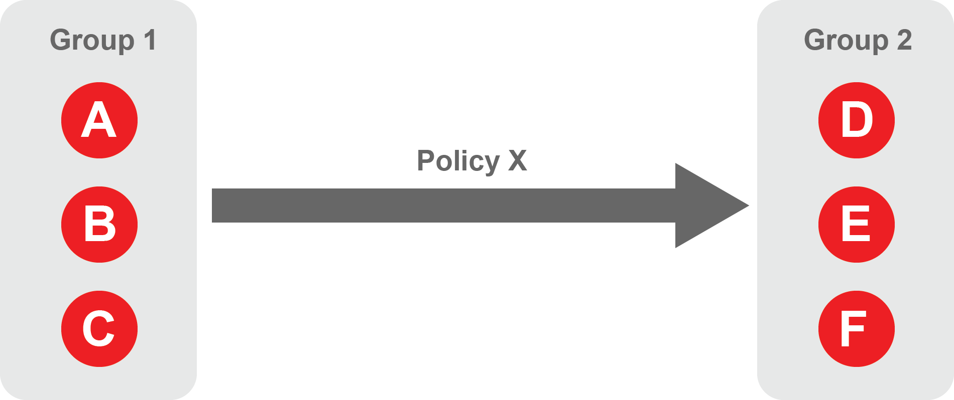
A policy defines how groups can interact. Groups are connected via policies, which form the foundation for BlastShield access control and segmentation management.
Each policy will have two sets of groups - "From" and "To".
The "From" set is one or more source groups.
The "To" set is one or more destination groups.
There is no limit to the number of groups in a given policy.
"From" Groups will have access to "To" Groups within the policy.
"To" Groups will not have access to "From" Groups within the policy.
Groups can be in one or multiple policies simultaneously.
 |
Create Groups
From the Orchestrator, select "Groups" from the left menu.
Select "Add New Group" from the Group List.
Enter a name for the new Group.
To add members to the new group, click the "Add Members" button.
If you adding users to the group then select the desired Users which you want to be associated with the Group from the "Users" box.
If you are adding Agents to the group then select the desired Agents which you want to be associated with the Group from the "Agents" box.
If you are adding Gateway Endpoints then select the desired Endpoints from the "Endpoints" box.
Alternatively, you can leave the members list empty and add/modify new members later.
Click "Add Members" to save the members.
Click "Save" to save the new group.
Repeat, if required, to ensure you have one group for your endpoints and one group for your users, which is the minimum you will need in order to define the access policy.
Please refer to the following video, which is an example of creating one group for your users and one group for Host Agents.
Create a Policy to link your Groups
Note
Users and Agents must be a member of a group for them to be used in a policy.
Select "Policies" from the left menu.
Select "Add New Policy" from the Policy List.
Enter a name for the new Policy.
Select desired "From" Groups to be associated with the new Policy.
Select desired "To" Groups to be associated with the new Policy.
Save the new Policy.
Policies are directional, so that you can control the direction in which connections may be initiated. Typically for remote access use-cases your policy would be from the "user group" to the "server group" so that users may start connections to the servers, but servers cannot start connections to users. You can create bi-directional permissions by using two policies.
The following video shows an example of creating an access Policy between a group of remote workers and a group of servers. The policy gives the remote workers authorisation to access the server group.
Important
Upgrading the Gateway.
When running as a container, the Gateway must be upgraded by modifying the container to use a newer image.