VMware Gateway deployment
This article explains how to install the BlastShield™ Gateway OVA in VMware ESXi 7.
A Gateway deployed on an ESXi platform can be configured to support any of the following addressing modes:
Source+Destination NAT
Destination NAT
MAC Address
VLAN
Gateway addressing modes are explained in more detail here: Gateway Addressing Modes
Gateway use cases are described here: Gateway types and their use cases
A VMware ESXi7 hypervisor with admin access.
A BlastShield™ Orchestrator with administrator access.
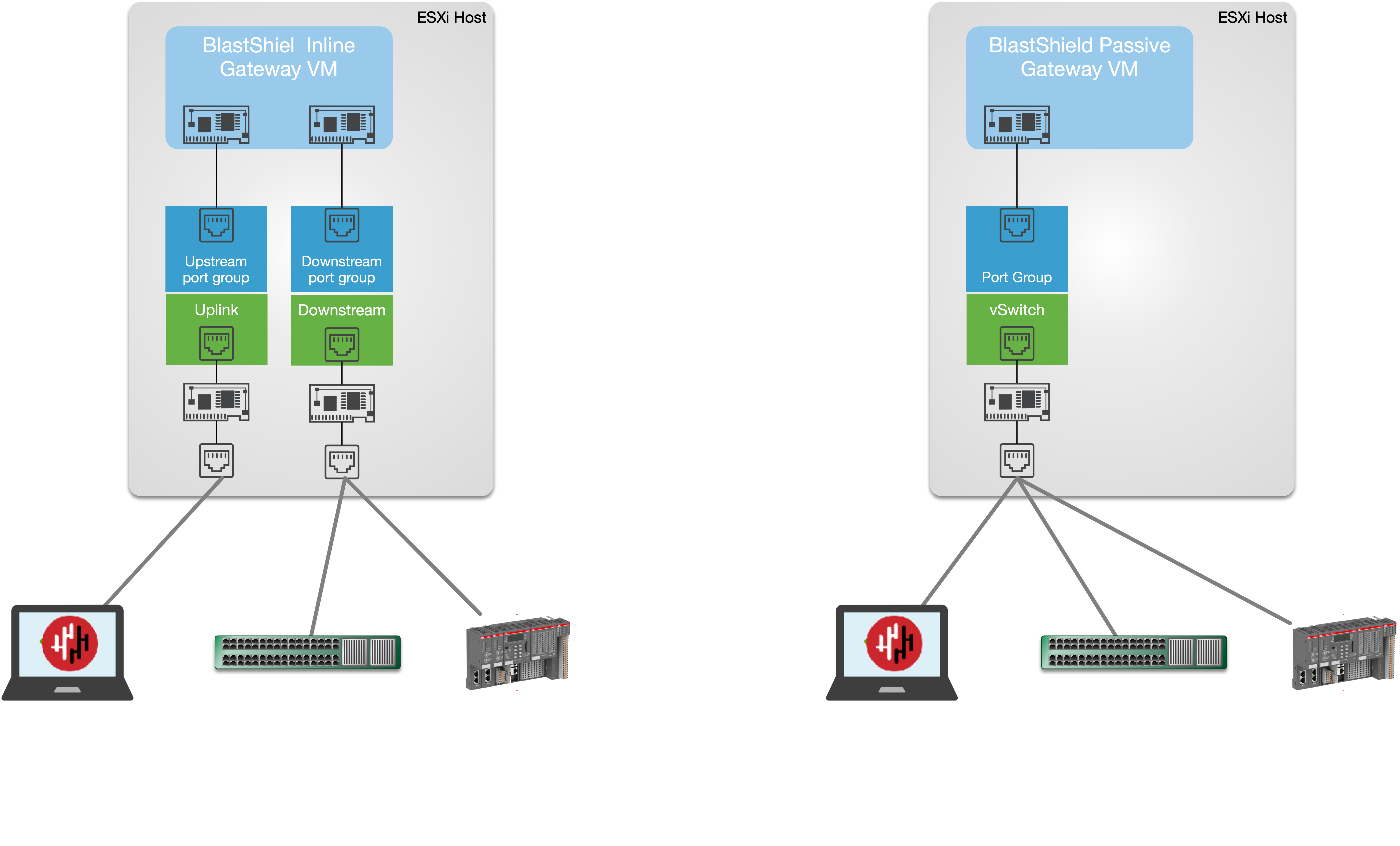
The hardware requires a minimum of one physical NIC for a passive Gateway deployment or at least two physical NICs for an inline Gateway deployment.
A network connection for the Gateway upstream interface with connectivity to the Orchestrator.
Outbound UDP ports to all required destinations.
Resolution of DNS requests must be supported by the network.
Create a new Gateway in the Orchestrator
From the Orchestrator, select "Gateways" from the left Menu.
Select Add New Gateway from the Gateway List.
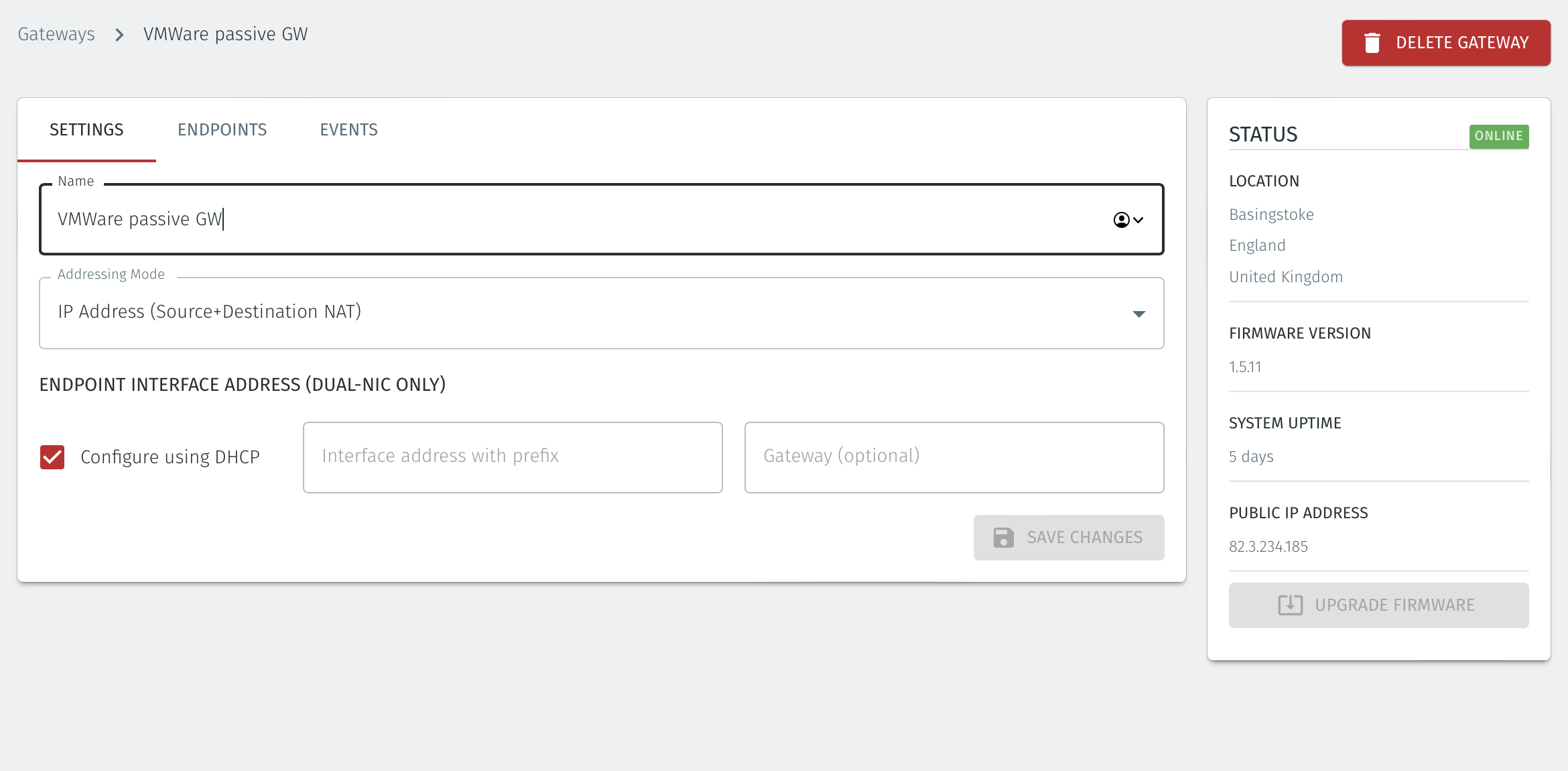
Enter a Name for the new Gateway.
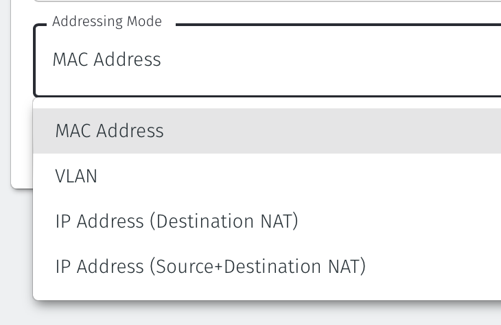
Set the Addressing Mode:
For MAC Addressing mode, click on MAC Address as the Addressing Mode.
For VLAN adressing mode, click on VLAN.
For Destination NAT addressing mode, click on IP Address (Destination NAT).
For Source and Destination NAT addressing mode, click on IP Address (Source+Destination NAT).
Endpoint Interface Settings.
The following steps apply only to Gateways using NAT addressing modes.
If you are using the Gateway in a single NIC configuration, leave the Endpoint Interface Settings as default.
If you are using the Gateway in a dual NIC configuration, then configure the Endpoint Interface Settings:
If you want the endpoint interface to get it's IP address via DHCP, then leave the configure using DHCP box checked.
If you want to manually set the endpoint interface IP address , then un-check the configure using DHCP box.
Set the Interface address with prefix field to the same IP address as the router which the Gateway is replacing. Use CIDR format.
If you will be onboarding endpoints which are not within the subnet you specified with the interface address above, then enter the IP address of the gateway required to reach the endpoints in the Gateway (optional) field.
To enable NAT for connections coming from endpoints to the external upstream network, i.e those connections allowed by egress policies, then enable NAT external connections by checking the box.
To enable the Gateway to forward non-endpoint connections from the protected network to the public side of the Gateway, check the Forward connections for non-endpoint addresses box. This will allow devices which are situated on the protected network side of the Gateway, which are not provisioned as endpoints on the Gateway, to forward traffic out through the Gateway.
Leave the Subnet to allocate endpoint addresses from blank if you want the system to allocate the overlay IP address (default). If you want to specify the subnet, then enter it here in CIDR format.
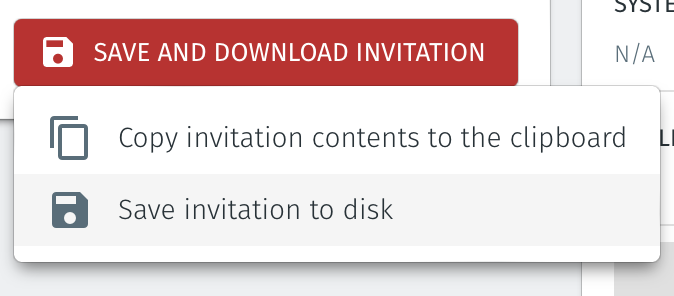
Select Save and Download Invitation.
Select the option Save Invitation to disk to download the invitation file to your local computer. You will need this file later when you install the Gateway.
Download the Gateway OVA file from here and keep it available so that you can upload it to your ESXi server.
Install the BlastShield Gateway™ OVA file on the ESXi client.
You will need the Invitation (.bsi) file and the OVA file from the previous steps to Install the Gateway OVA.
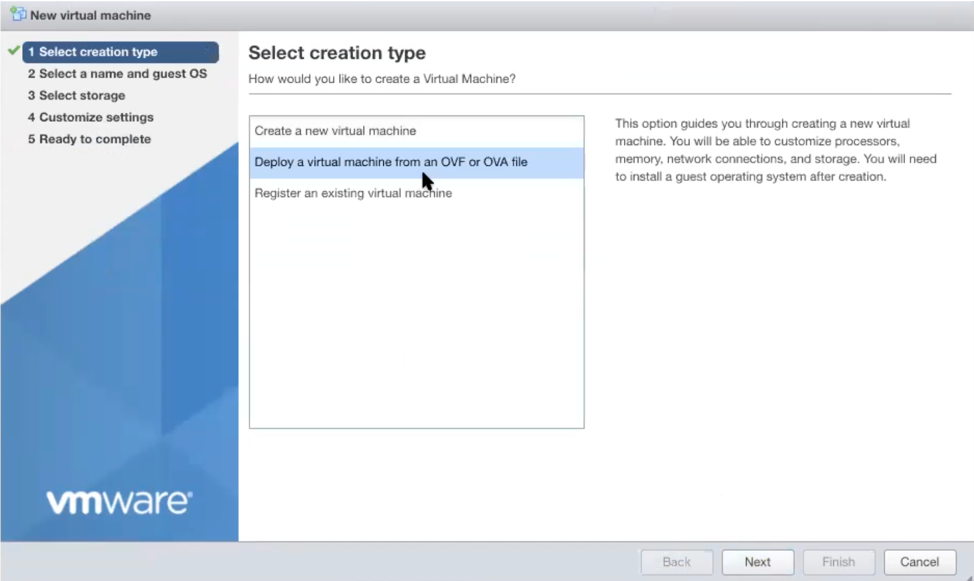
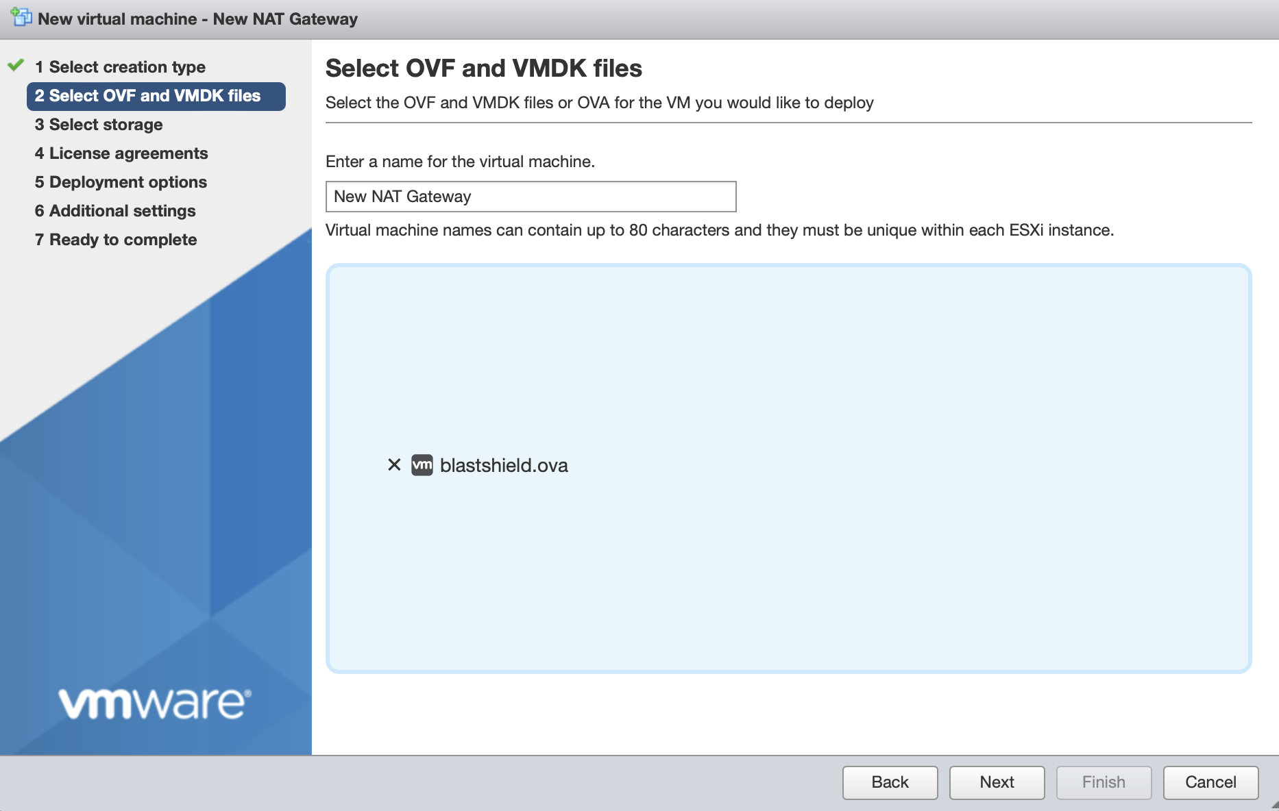
From the ESXi host, go to Virtual Machines > Create/Register VM > Create a virtual machine from an OVF/OVA file
Give the new Gateway a name and select the BlastShield™ OVA file which you downloaded in the previous step.
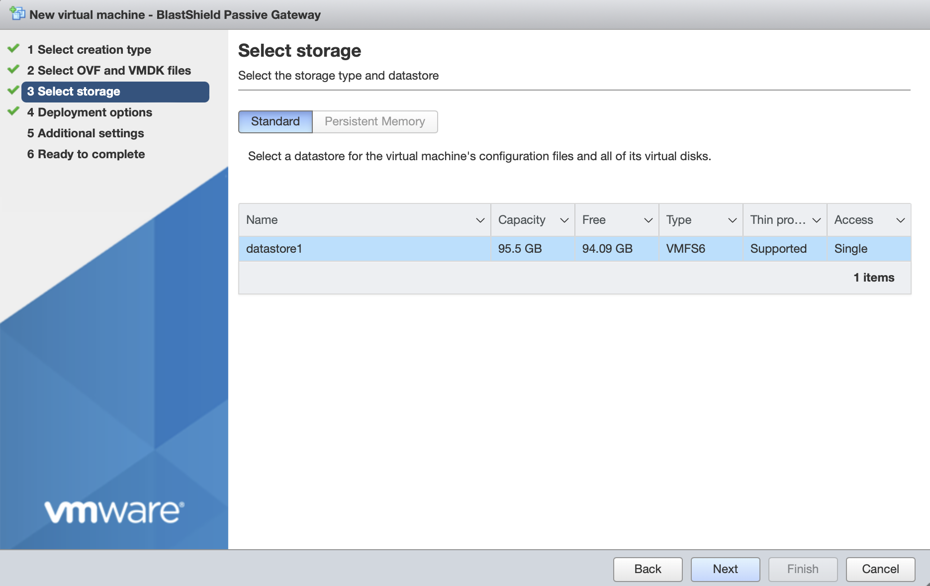
Leave the default datastore option.
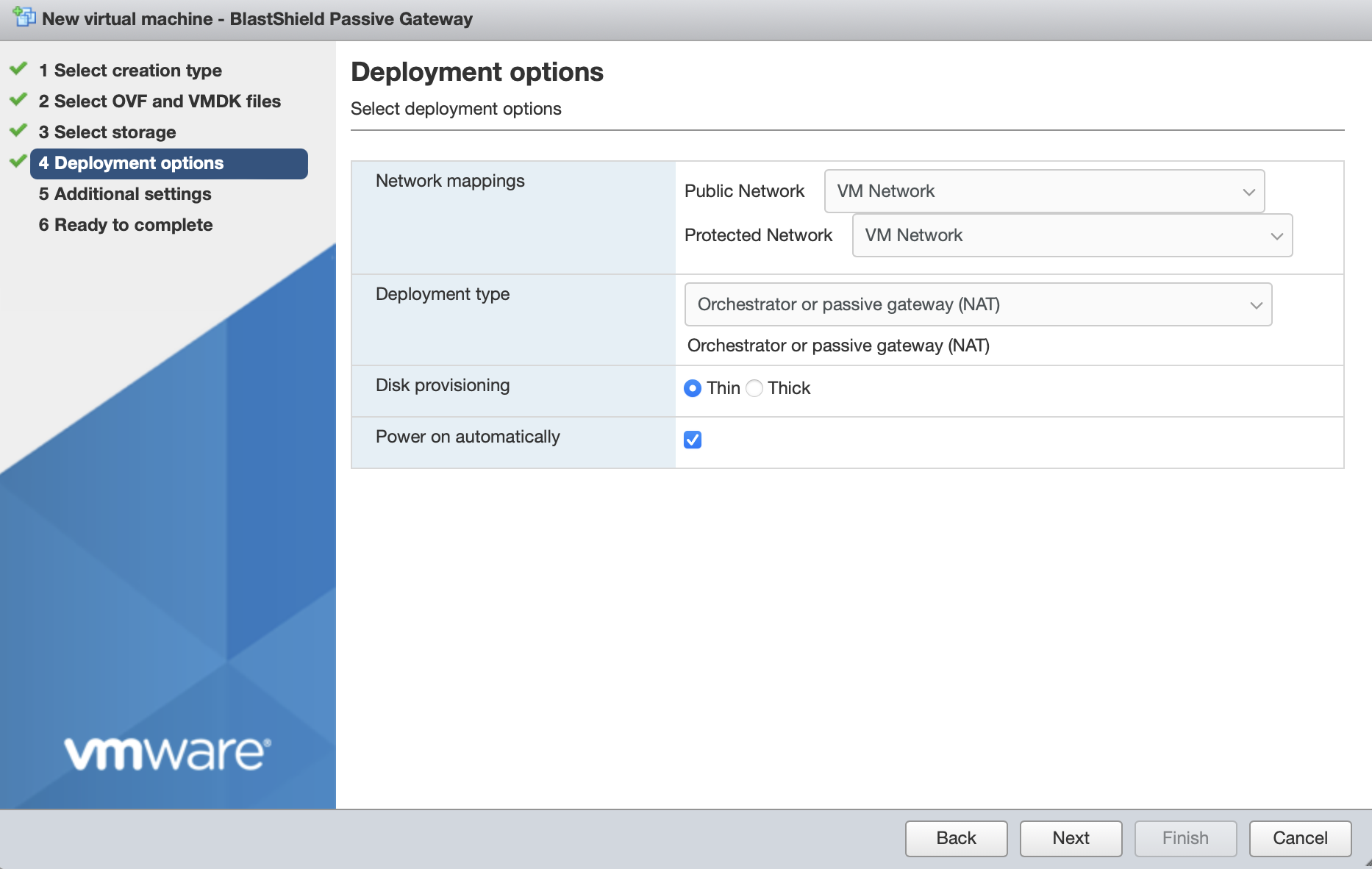
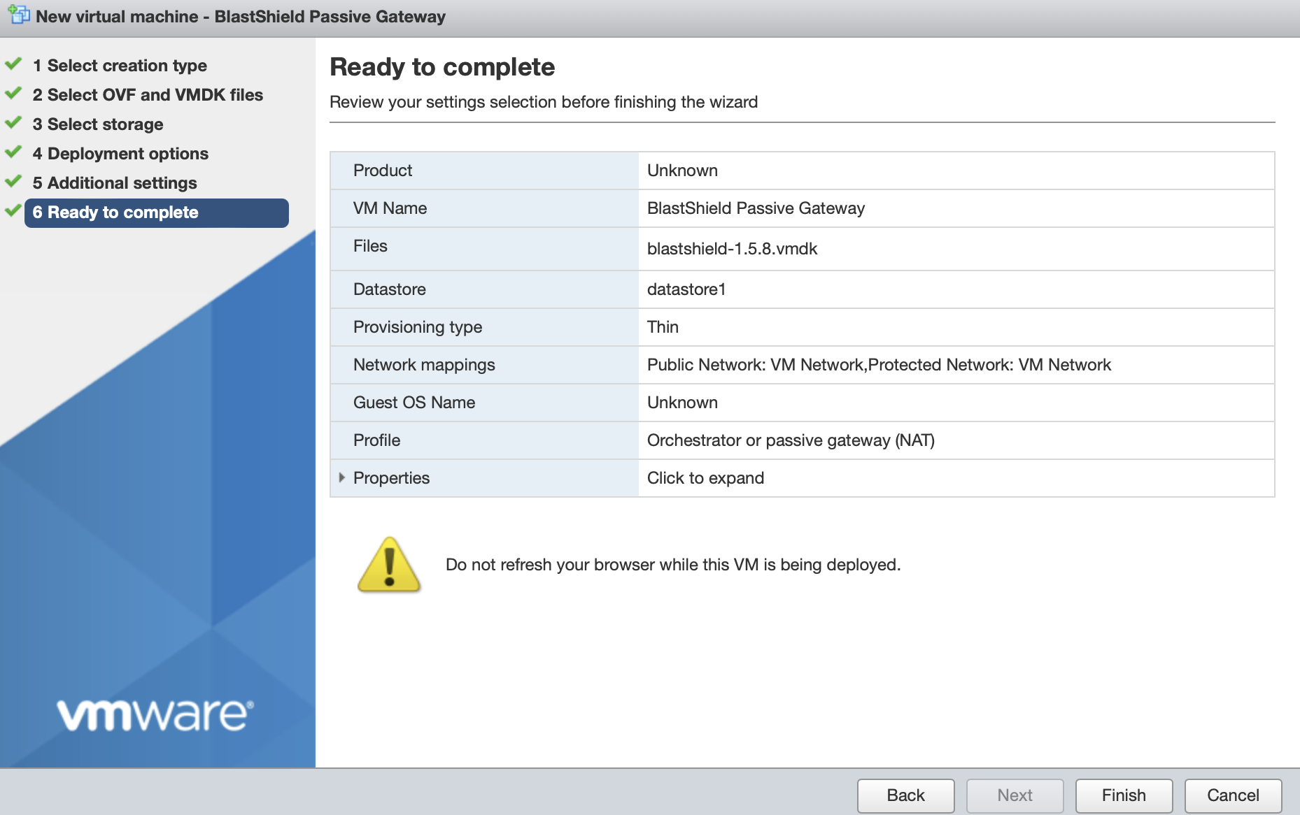
Deployment options. Chose one from the two options below.
If you are deploying a Passive Gateway with a single NIC:
Set the Network mapping > Public Network and Protected Network to the same port group on the external physical NIC.
The Deployment type should be set to Orchestrator or passive gateway (NAT).
If you are deploying an Inline Gateway with two or more NICs:
Set the Network mapping > Public Network to the port group on the upstream NIC.
Set the Network mapping > Protected Network to the port group on the downstream NIC.
If you will use additional downstream interfaces, you can add them later in the Gateway console menu.
The Deployment type should be set to Inline Gateway.
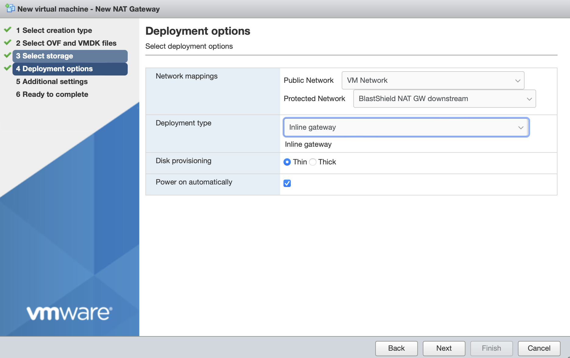
Disk provisioning' and 'Power on automatically' should use the default settings.
Click Next.
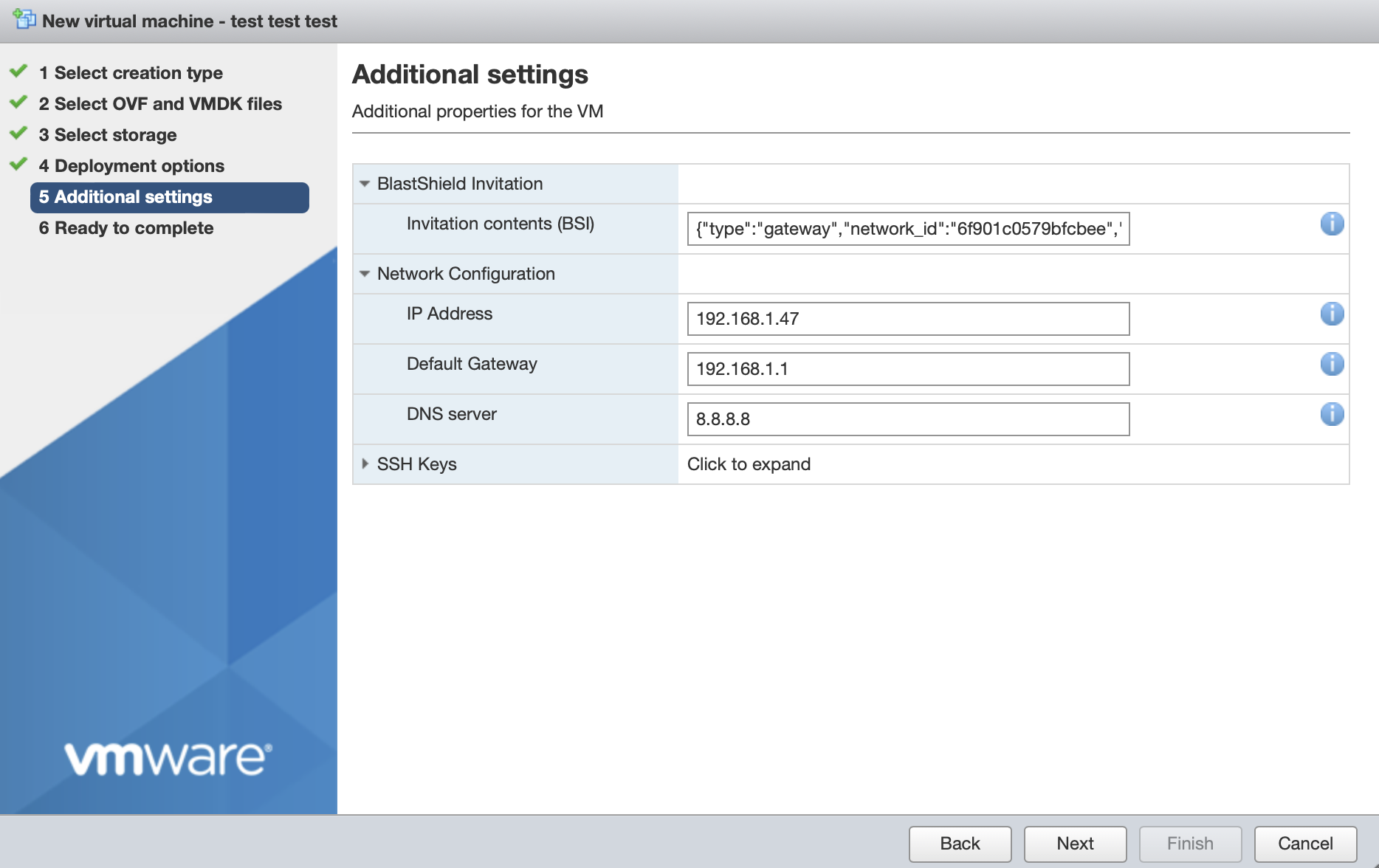
In Additional Settings, add the contents of the bsi file.
In the BlastShield Invitation section, paste the contents of the Gateway BSI file (from Step 1, above) into the Invitation contents box.
Network Configuration
The network configuration sets the Gateway's local IP address, default gateway and DNS. For an inline Gateway, this refers to the upstream interface.
To use DHCP to assign the IP address, default gateway and DNS, leave all three boxes blank in the Network Configuration section. This is the default option.
If you are setting a manually assigned IP address, default gateway and DNS, then enter their IP addresses as described below.
In the IP Address field, enter the IPv4 address and prefix length of the upstream network interface.
In the Default Gateway field, enter the default gateway IPv4 address for the upstream network interface.
In the DNS server field, enter the IPv4 address for the upstream network interface. If left blank, the Gateway will try public DNS.
For a Gateway deployment, do not add an SSH key here. The Orchestrator will provision the Administrator SSH key into the Gateway (this is the SSH key which was configured when the Orchestrator was first installed).
The picture below shows example manual settings. Please use settings appropriate to your network.
Click next, then click 'Finish' to complete the configuration and launch the VM.
You can verify the Gateway has started by watching the console output in the hypervisor. when the Gateway is up, then the status in the Orchestrator will indicate 'online' as shown in the image below.
Troubleshooting if your Gateway status does not come Online
Ensure you have pasted the contents of the bsi file from the Orchestrator into the Additional settings step of the Create/Register VM procedure when you install the Gateway OVA on the hypervisor.
If your hypervisor environment is not running a DHCP server, make sure you have manually configured an IP address in the Network Configuration section of the Additional settings step of the Create/Register VM procedure on the hypervisor. You can manually enter an IP address, default gateway and DNS server in the Network Configuration.
Ensure there is outbound network access on the hypervisor, so that the Gateway VM can communicate with the BlastShield™ Orchestrator.
From within the Orchestrator, select "Gateways" from the left Menu
Select the desired Gateway from the Gateway List
Select "Add New Endpoint"
Enter a name for the new endpoint
Check "Endpoint Enabled" to Enable it when done.
The IP address is auto-populated.
Configure the endpoint Destination field.
If the Gateway is using either of the NAT addressing modes, enter the endpoint's private IPv4 LAN address or hostname.
If the Gateway is using MAC address addressing mode, enter the endpoint's MAC Address.
If the Gateway is using VLAN addressing mode, enter the endpoint's VLAN ID.
Click on Save Changes to confirm.
If the endpoint is reachable from the Gateway the the status of the endpoint will show as ONLINE.
If it does not show as online, then check the connectivity between the Gateway and the endpoint device.
For endpoints on Gateways which use destination NAT addressing mode only, add a route on the endpoint to the BlastShield 172.16.0.0/16 overlay network via the Gateway's endpoint interface as the next hop..
About Groups
Groups allow you to micro-segment users and endpoints. A group is a logical collection of endpoints and/or users that are grouped together. Groups are connected via policies, which form the foundation for BlastShield access control and segmentation management.
Any combination of endpoints and/or users can be grouped together.
There is no limit to the number of endpoints and/or users that can be in a group.
Endpoints and users can be in one or multiple groups simultaneously.
Groups are linked together via policies to provide access between endpoints.
By default, endpoints/users cannot access or have visibility to other endpoints/users unless they are granted access via a policy
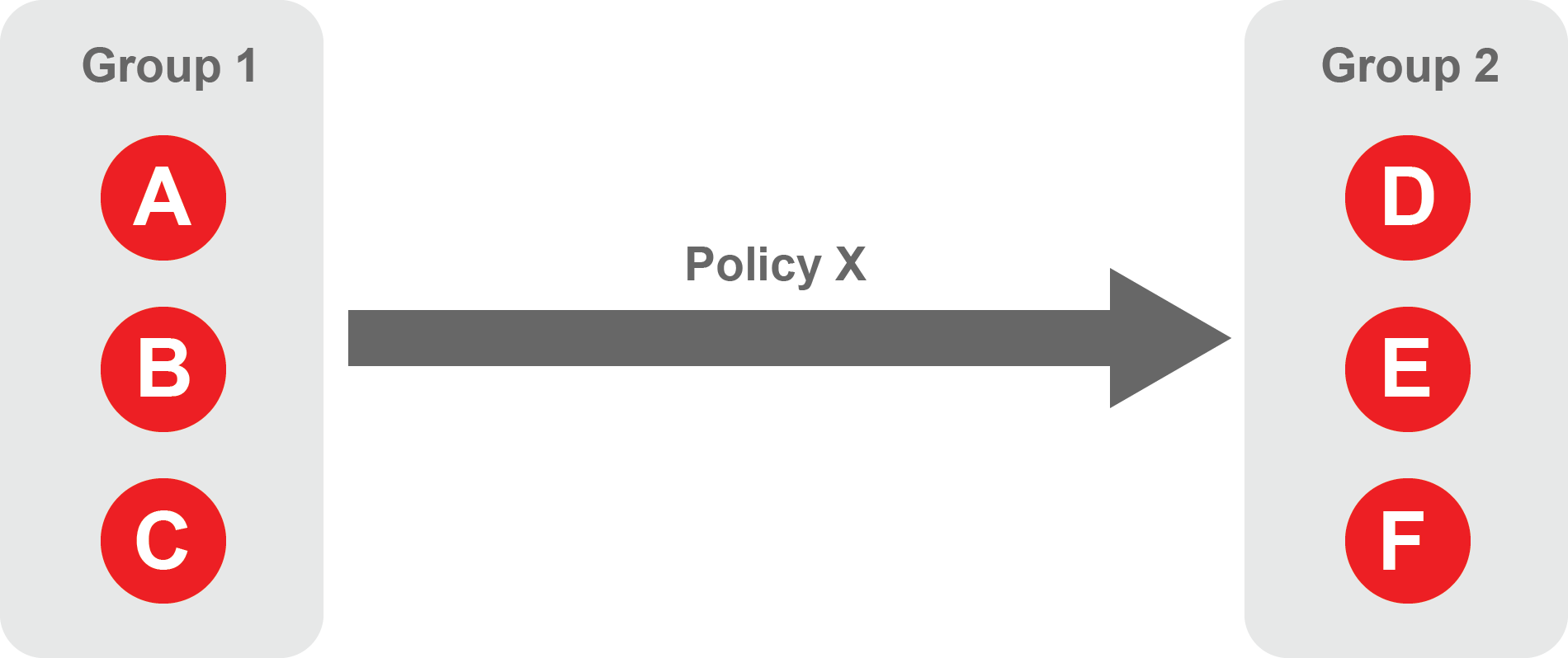
About Policies
A policy defines how groups can interact. Groups are connected via policies, which form the foundation for BlastShield access control and segmentation management.
Each policy will have two sets of groups - "From" and "To".
The "From" set is one or more source groups.
The "To" set is one or more destination groups.
There is no limit to the number of groups in a given policy.
"From" Groups will have access to "To" Groups within the policy.
"To" Groups will not have access to "From" Groups within the policy.
Groups can be in one or multiple policies simultaneously.
 |
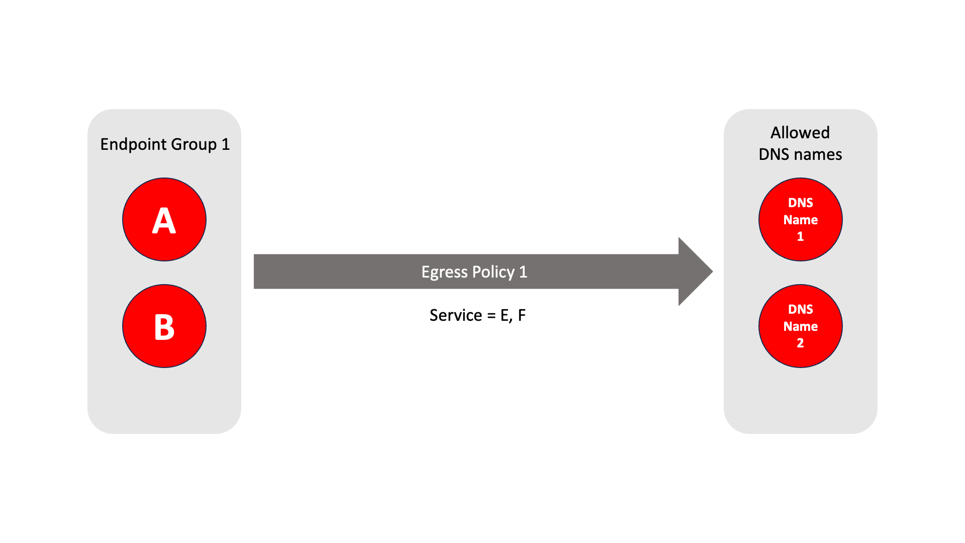
About Egress Policies
Egress policies allow you to control external network access for Gateway endpoints which are isolated behind a Gateway. This enables endpoints to connect to external entities, for example to download a software update or to connect to an NTP server.
The endpoint group contains the endpoints which the policy applies to.
The allowed services are E and F.
The network prefixes or DNS names define the allowed external network destinations for the endpoint group.
 |
Create Groups
From the Orchestrator, select "Groups" from the left menu.
Select "Add New Group" from the Group List.
Enter a name for the new Group.
To add members to the new group, click the "Add Members" button.
If you adding users to the group then select the desired Users which you want to be associated with the Group from the "Users" box.
If you are adding Agents to the group then select the desired Agents which you want to be associated with the Group from the "Agents" box.
If you are adding Gateway Endpoints then select the desired Endpoints from the "Endpoints" box.
Alternatively, you can leave the members list empty and add/modify new members later.
Click "Add Members" to save the members.
Click "Save" to save the new group.
Repeat, if required, to ensure you have one group for your endpoints and one group for your users, which is the minimum you will need in order to define the access policy.
Please refer to the following video, which is an example of creating one group for your users and one group for Host Agents.
Create a Policy to link your Groups
Note
Users and Agents must be a member of a group for them to be used in a policy.
Select "Policies" from the left menu.
Select "Add New Policy" from the Policy List.
Enter a name for the new Policy.
Select desired "From" Groups to be associated with the new Policy.
Select desired "To" Groups to be associated with the new Policy.
Save the new Policy.
Policies are directional, so that you can control the direction in which connections may be initiated. Typically for remote access use-cases your policy would be from the "user group" to the "server group" so that users may start connections to the servers, but servers cannot start connections to users. You can create bi-directional permissions by using two policies.
The following video shows an example of creating an access Policy between a group of remote workers and a group of servers. The policy gives the remote workers authorisation to access the server group.
Create an Egress Policy
Egress policies are required only if a Gateway endpoint requires external network access.
Egress policies allow you to control external network access for Gateway endpoints which are isolated behind a Gateway. This enables endpoints to connect to external entities, for example to download a software update or to connect to an NTP server.
The Egress Policy menu in the Orchestrator allows policies for external network access to be configured on a per-endpoint group basis, where the groups are defined in the Orchestrator Groups menu. Allowed destinations may be defined either by network prefix or by DNS names and the policy may be further controlled by specifying an allowed service. An egress policy may be enabled or disabled from the Orchestrator if the external network access is only temporary.
From within the Orchestrator, select Egress Policies from the left Menu.
Select the red "Add New Policy" icon.
Enter a name for the new Policy.
Check the Policy Enabled box to enable the policy and continue with the configuration.
Select the desired endpoint Groups to be associated with the new Egress Policy in the Endpoint Groups dropdown box
Select any optional Services groups to be associated with the new Policy in the Services dropdown box.
If you want to allow external DNS queries in the policy, then check the Allow all DNS queries box.
Specify the allowed destinations for the Egress Poicy as required using the following options:
In the Allowed Prefixes box, define an allowed external IP address and prefix
in the Allowed DNS Names box, define an allowed external DNS name.
To allow recursive DNS queries, check the Recursive box.
Click Save Changes to save the new Egress Policy.