Active and Passive Gateways
The BlastWave Gateway has two different modes of operation, active and passive, which provide different functionality with respect to how how Endpoints communicate and how they are isolated from the local network.
The degree of Endpoint isolation can be optimised to suit your access requirements by configuring the Gateway in the appropriate mode, either Active or Passive. In both cases BlastShield provides Zero-trust secure remote access, micro-segmentation of Gateway Endpoints, remote user authorized with MFA and encypted peer-to-peer connectivity.
Active Gateway
All protected Endpoints downstream from an Active Gateway will be rendered invisible to the network underlay, and access control will be managed by BlastShield™ policy. The Gateway provides isolation at the network layer, providing a virtual-air gap and inhibiting unauthorised lateral movement between the protected endpoints. The endpoints will be unable to communicate with non-BlastShield nodes.
An active Gateway is configured by setting the Gateway addressing mode to either MAC Address or VLAN.
Passive Gateway
The Endpoints of a Passive Gateway are able communicate freely on their local LAN whilst at the same time secure remote access for users over the BlastShield™ network to these Endpoints is managed by the Gateway.
A passive Gateway is configured by setting the Gateway addressing mode to either IP Address (Source+Destination NAT) or IP Address (Destination NAT).
Active and Passive Gateway Comparison
This table summarises the features of the active and passive Gateway types.
Features | Active Gateway | Passive Gateway |
|---|---|---|
Zero-trust secure remote access | Yes | Yes |
Users authenticated with MFA | Yes | Yes |
Micro-segmentation of Gateway Endpoints | Yes | Yes |
Endpoints invisible to and isolated from unauthorized external users | Yes | Yes |
Endpoints invisible to and isolated from unauthorized internal users | Yes | No |
Control of lateral movement in the protected LAN. | Yes | No |
Gateway Addressing Mode configuration | MAC Address VLAN | IP Address (NAT) |
On an Active Gateway, the allowed Endpoints are configured either using the Endpoint MAC-addresses or a VLAN ID per-Endpoint, which makes it suitable for protecting OT/IoT assets, legacy servers when isolation of the asset from unauthorised users is required. Such virtual air-gapping can be used when critical assets require protection.
All protected Endpoints downstream from an Active Gateway are rendered invisible to the network underlay, and access control will be managed by the BlastShield™ network. The Gateway provides isolation at the network layer, providing a virtual-air gap and inhibiting unauthorised lateral movement between the protected endpoints. By default, the endpoints will be unable to communicate with non-BlastShield nodes, however if an Endpoint needs to connect to a non-BlastShield™ node, this may be configured using the Enhanced Endpoint Connectivity feature, which is explained at the end of this article.
In an active Gateway configuration, two physical Ethernet interfaces are required on the Gateway, one for the Endpoint-side network and the other for the local network. This is configured during the Gateway setup process.
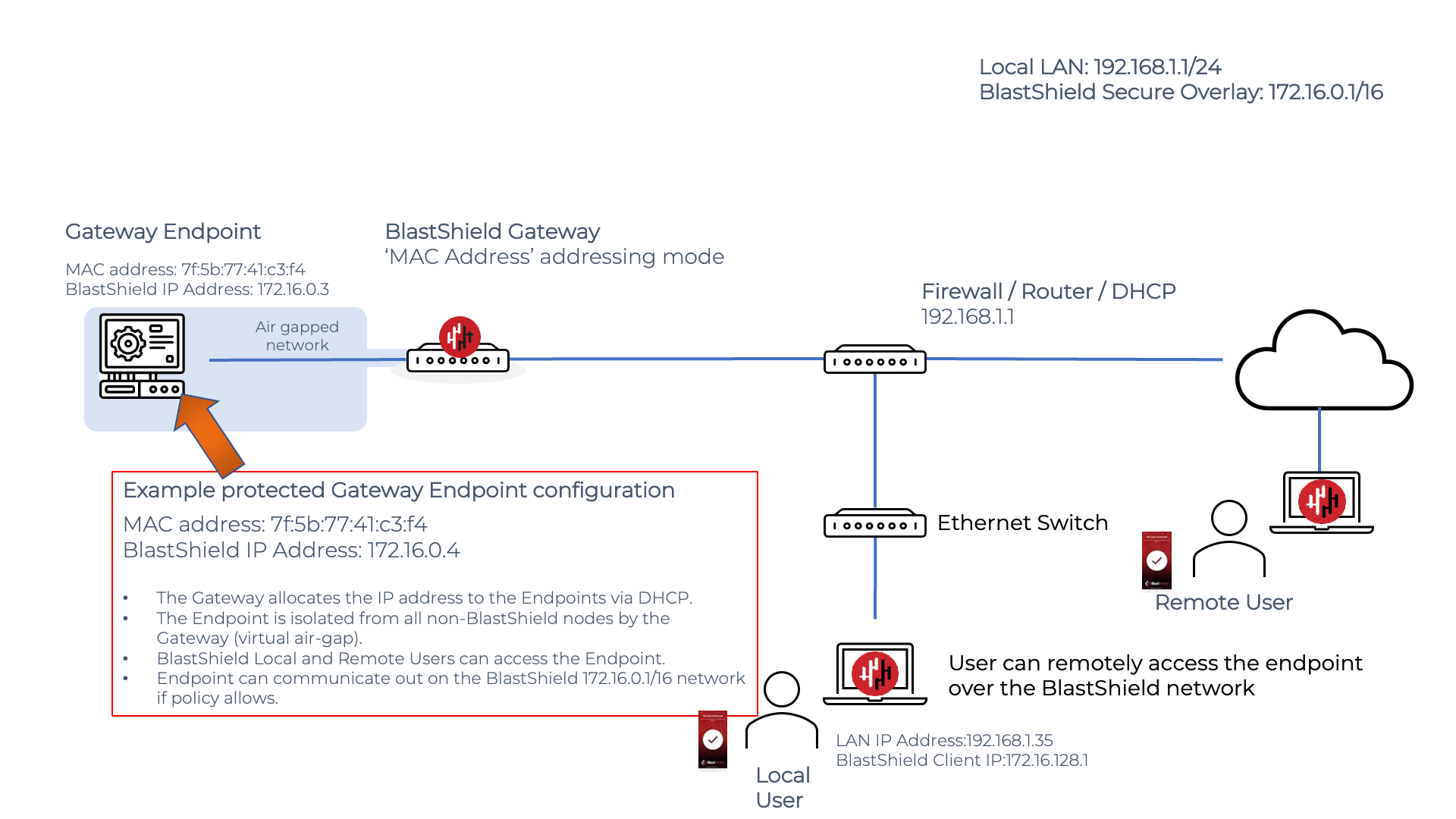
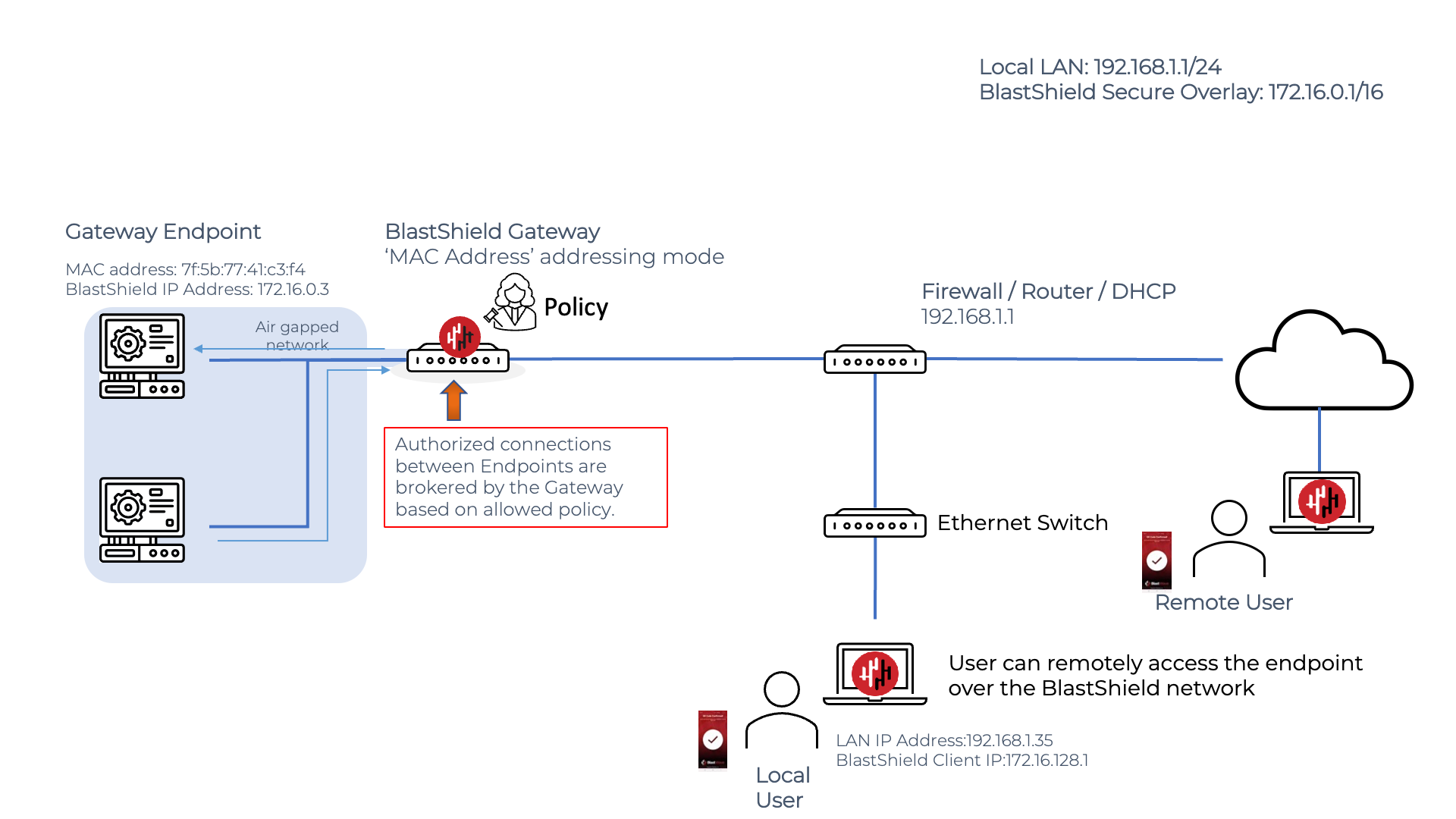
Active Gateways are configured using either MAC Address or VLAN addressing modes. The diagram below shows MAC Address mode used to configure an Endpoint to an Active Gateway.
Secure remote access to and Endpoint protected by an Active Gateway
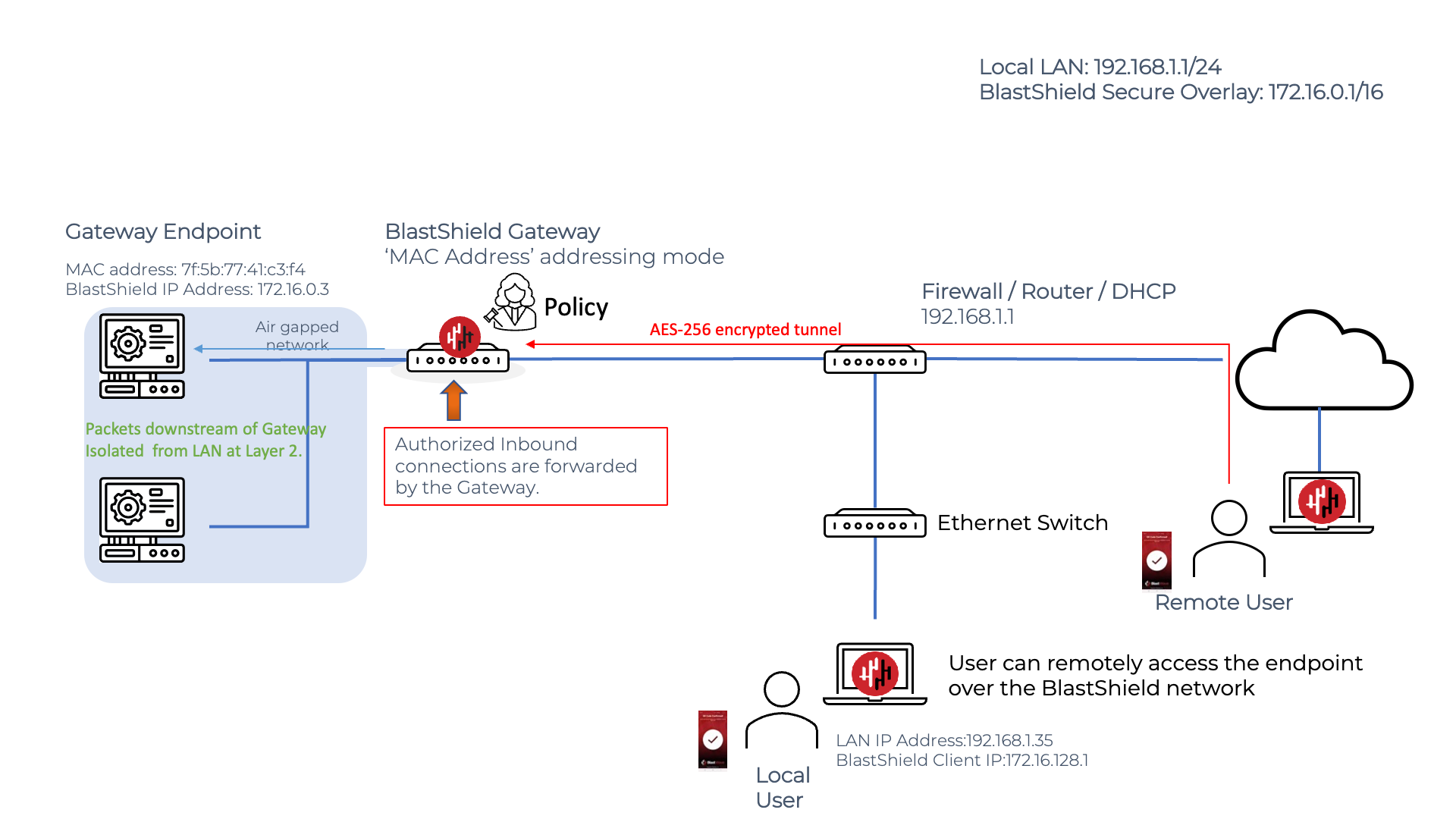
The Gateway will allow another BlastShield node (User, Agent or other Endpoint) to connect to its Endpoint(s) if there is a corresponding policy allowing the connection. In this case, the Gateway will forward allowed packets from the source to the Endpoint.
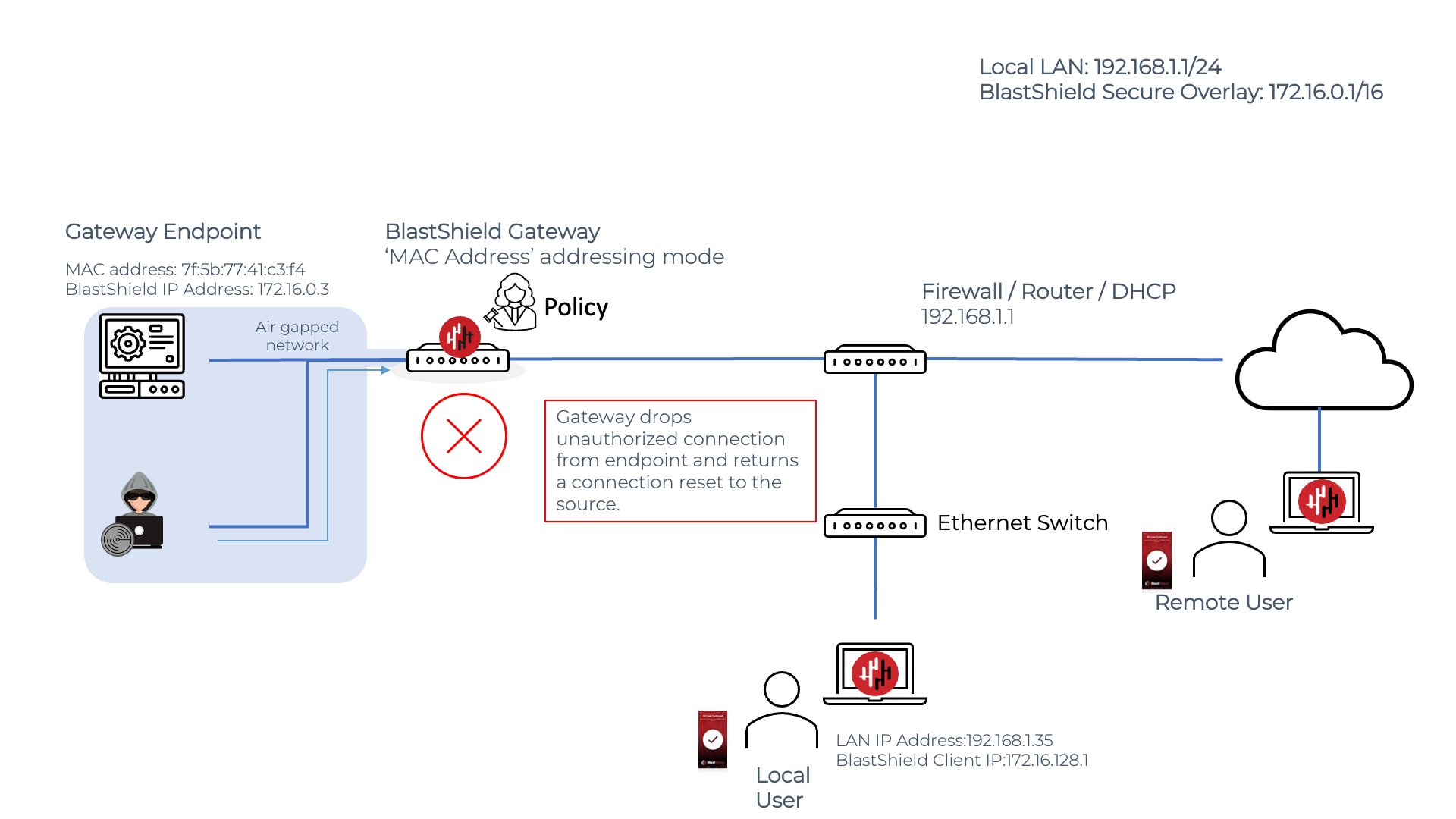
Endpoint isolation and invisibility
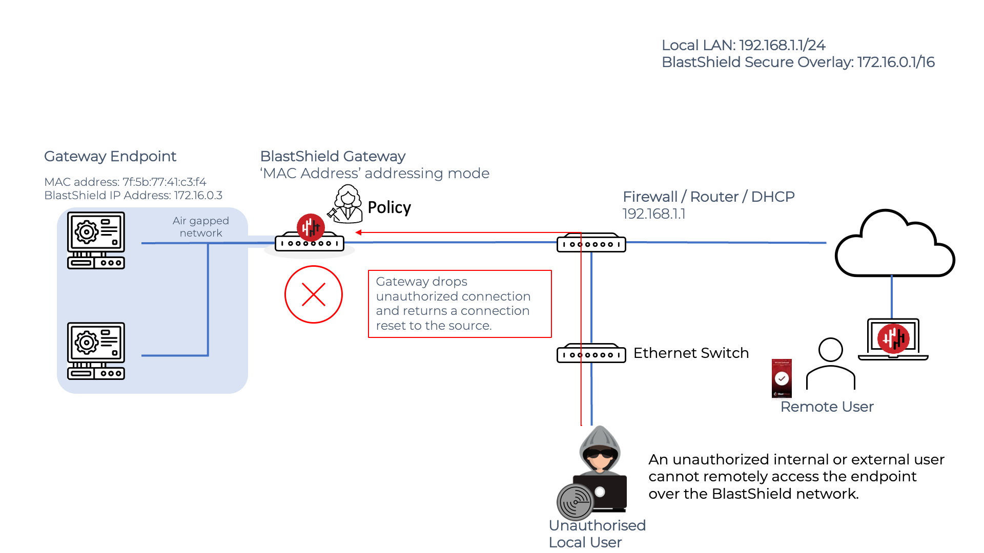
Any unauthorized connection attempt to an Endpoint behind an active Gateway will have its packets dropped and a connection reset sent to the originator. The Gateway manages connections at Layer 2, so the Gateway is able to render protected Endpoints completely isolated at the network layer to unauthorized users both inside and outisde the network. Endpoints can be made invisible and will behave as if they are virtually air-gapped.
Endpoint communication on an Active Gateway
The Active Gateway will broker all Endpoint communications and will only forward packets if allowed by policy. In the example below the second Endpoint is allowed to forward a packet to the first Endpoint and the Gateway forwards those packets between the Endpoints.
Protection against unauthorized lateral movement inside the LAN
If an Endpoint makes an unauthorised connection attempt, the Gateway will not forward the packet and the connection attempt will be rejected. In this way, the Gateway can control and block unauthorized lateral movement in the protected network. In the example below, an unauthorized user attempts to scan the downstream network, but the connection attempts are dropped by the Gateway because they are unauthorized.
Enhanced Endpoint connectivity
The Enhanced support for Gateway Endpoint connectivity feature allows Endpoints behind an active BlastShield™ Gateway to create external connections to non-BlastShield™ nodes. The default condition for an Endpoint that is protected by an active BlastShield Gateway is that the Endpoint may only communicate to other nodes in the BlastShield™ network to which it is authorized. The Enhanced Endpoint connectivity feature allows such Endpoints to establish a connection to a non-BlastShield™ node that is outside of the protected network.
This feature is typically used if communications are required from a node or nodes in the BlastShield™ network to a node which is outside of the BlastShield™ network, for example if the protected Endpoint must periodically upload log files to a centralized data store.
To achieve this, the BlastShield™ Gateway provisions a default gateway IP address via DHCP on to the protected Endpoint. This gives the Endpoint a forwarding route out of the BlastShield™ network to non-BlastShield™ IP address ranges.. The BlastShield™ Gateway will NAT such outbound connections from the BlastShield™ IP address range to non-BlastShield™ IP address ranges, allowing a connection to be established from the protected Endpoint to the non-Blastshield™ node.
The following diagram shows how the enhanced connectivity works. An Active Gateway (configured to use 'MAC address' as the addressing mode) is shown protecting a server Endpoint. This Endpoint has a protected IP address on the BlastShield network of 172.16.0.2 and in the default Endpoint configuration it would be isolated from non-BlastShield™ nodes due to the layer 2 isolation provided by the Gateway. With the Enhanced Endpoint Connectivity mode enabled, the protected endpoint may now open a connection to the non-BlastShield™ endpoint with IP 10.100.10.10.
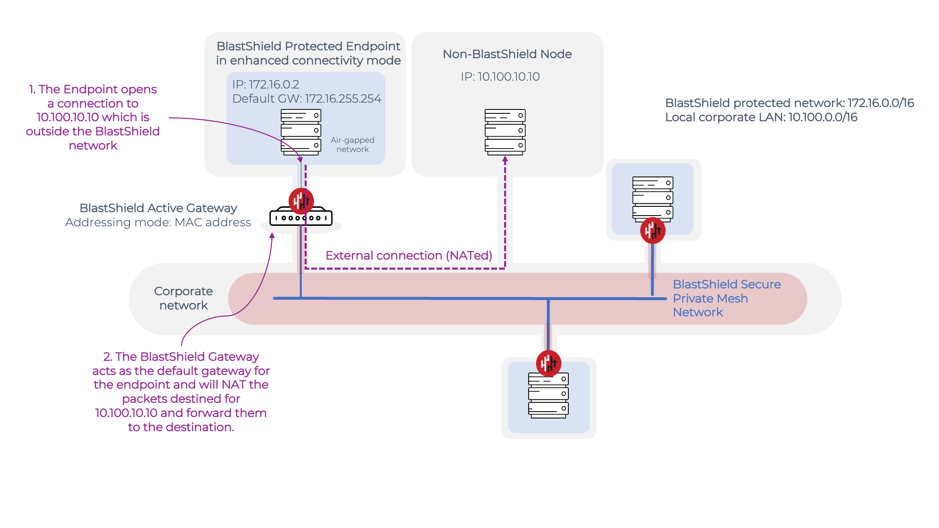
The enhanced connectivity works as follows:
When it boots up, the Endpoint requests an IP address from the BlastsShield™ Gateway.
The Gateway responds by allocating an IP address from the BlastShield™ network prefix to the Endpoint via DHCP. Because the Enhanced Endpoint Connectivity feature is enabled, the BlastShield™ Gateway also allocates a default gateway address in the DHCP offer.
When the Endpoint establishes a connection to 10.100.10.10 which is outside the BlastShield™ network, it uses the default gateway address for the connection.
The BlastShield™ Gateway receives packets destined for the default gateway address and will NAT these packets and then forward them to the 10.100.10.10 destination.
To learn how to configure the Enhanced support for Gateway Endpoint connectivity, please read the following article: Configure Enhanced Gateway Endpoint Connectivity
Introduction
The passive Gateway works by performing network address translation (NAT) on the protected Endpoint packets which makes it suitable for deploying on private cloud infrstructure and as a virtual machine.
Passive gateways can run in two different NAT modes; IP Address (Destination NAT) mode, and IP Address (Source and Destination NAT) mode. In both modes the the destination IP address gets translated from the address configured in the BlastShield™ overlay to the native IP address of the endpoint. The source address is handled differently:
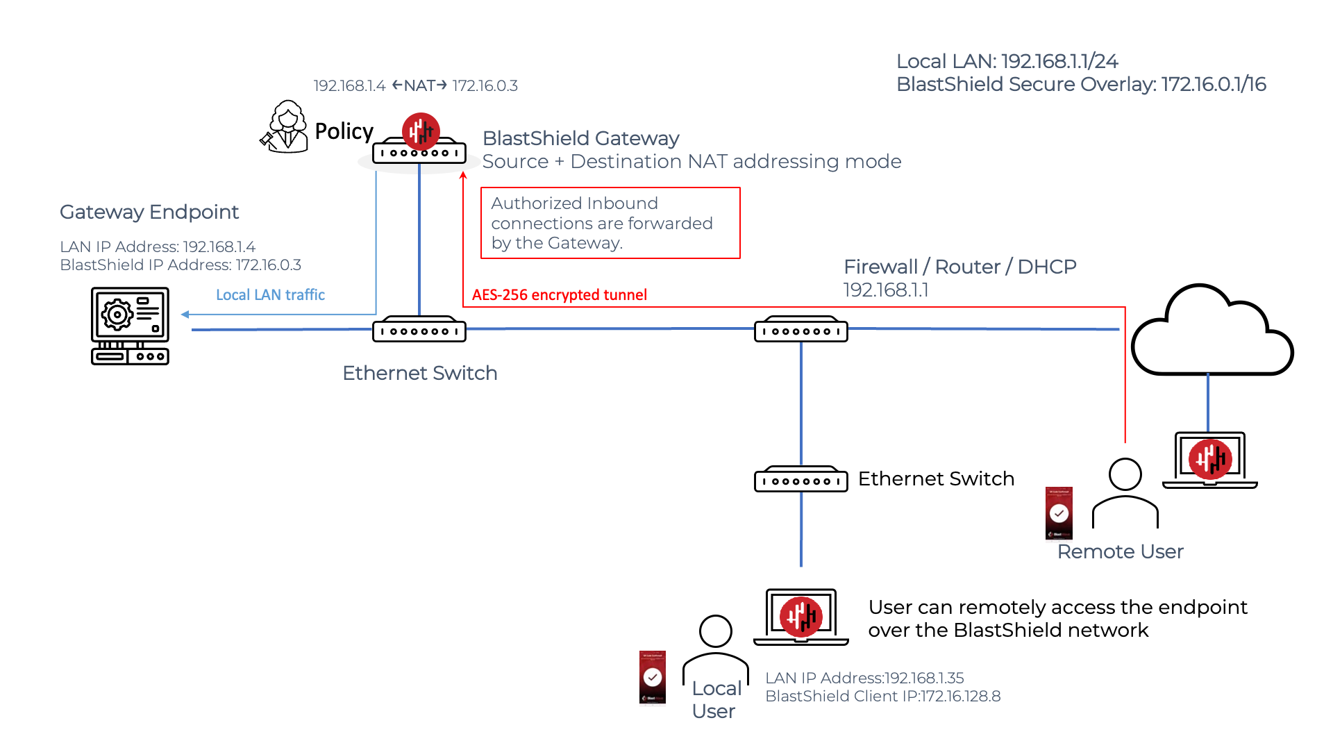
Source+Destination NAT
The Source+Destination NAT Gateway is designed to be deployed without requiring any routing changes on the Endpoints. The Gateway rewrites both source and destination addresses for all packets; the packets from the user will have the destination address rewritten to the one entered as the destination and the source address+port are translated to the gateway's local IP address, such that it appears as if the packet came from the gateway directly. This mode requires no routing changes, but endpoints can't connect back into the overlay as they don't have the route to do so, which makes it suitable for providing secure remote access to Endpoints.
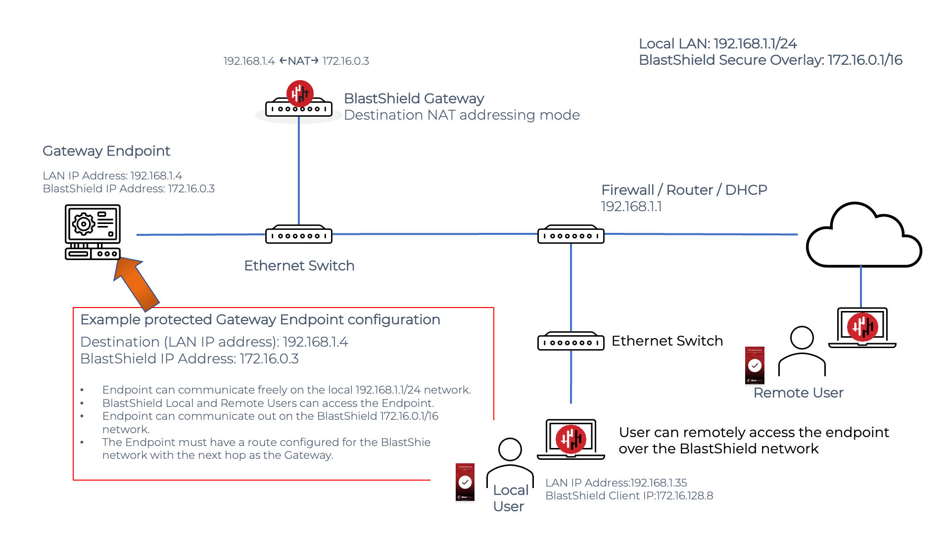
Destination NAT
The endpoint will see the source address as coming from the overlay IP prefix. The Gateway rewrites destination addresses for all packets; the packets from the user will have the destination address rewritten to the one entered as the destination. This requires a routing change in the endpoint for the endpoint to initiate connections to the BlastShield™ overlay network. It is suitable for both secure remote access to Endpoints and secure connections from Endpoints to other nodes in the BlastShield™ overlay.
In a passive Gateway configuration, only one physical ethernet interface is required on the Gateway, which will handle traffic in both directions. This is configured during the Gateway setup process.
The source+destination NAT Passive Gateway
The Gateway rewrites both source and destination IP addresses for all packets. The packets from the user will have the destination address rewritten to the one entered as the destination. The source address + port will be transformed to look as if it came from the gateway directly.
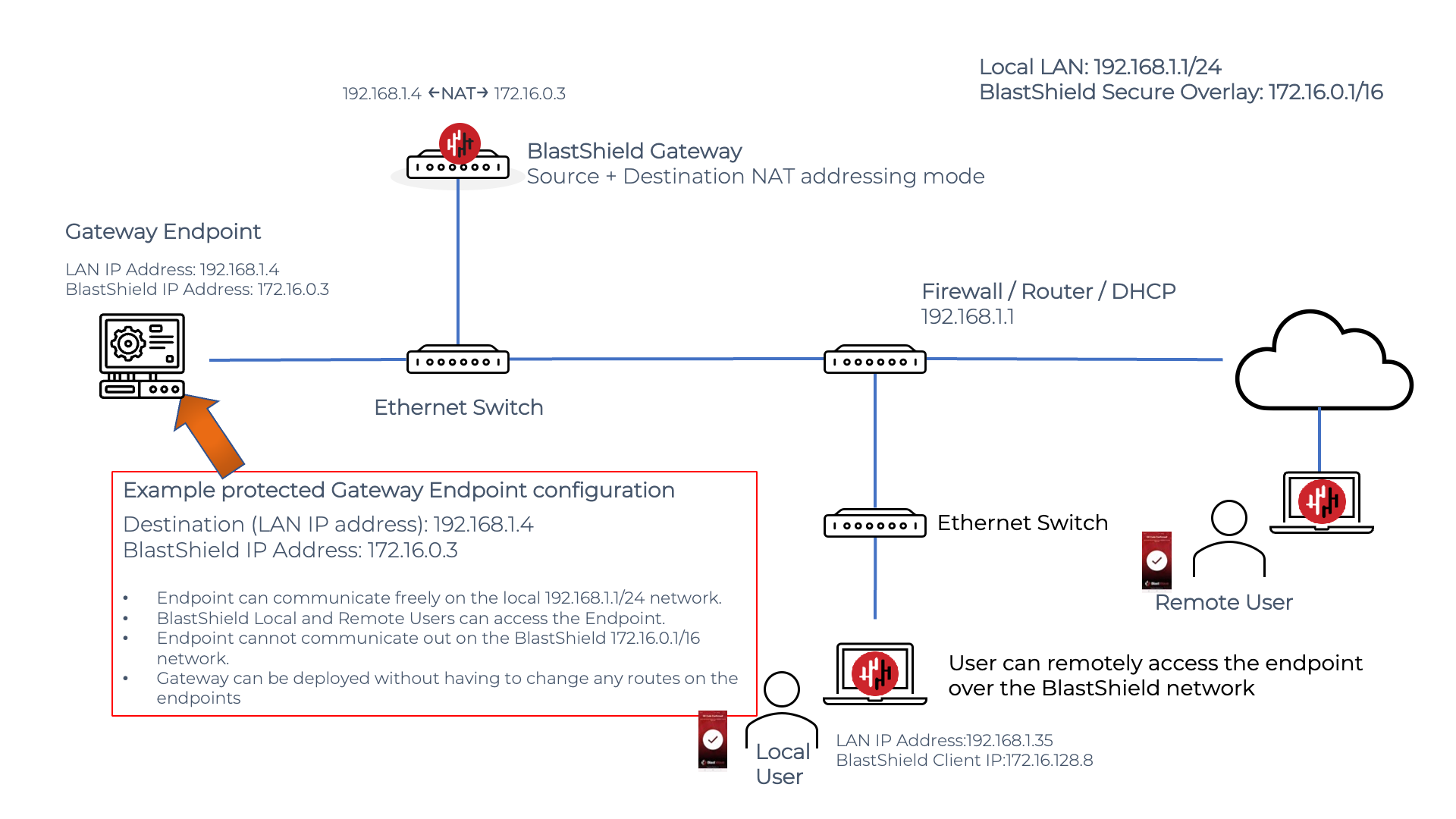
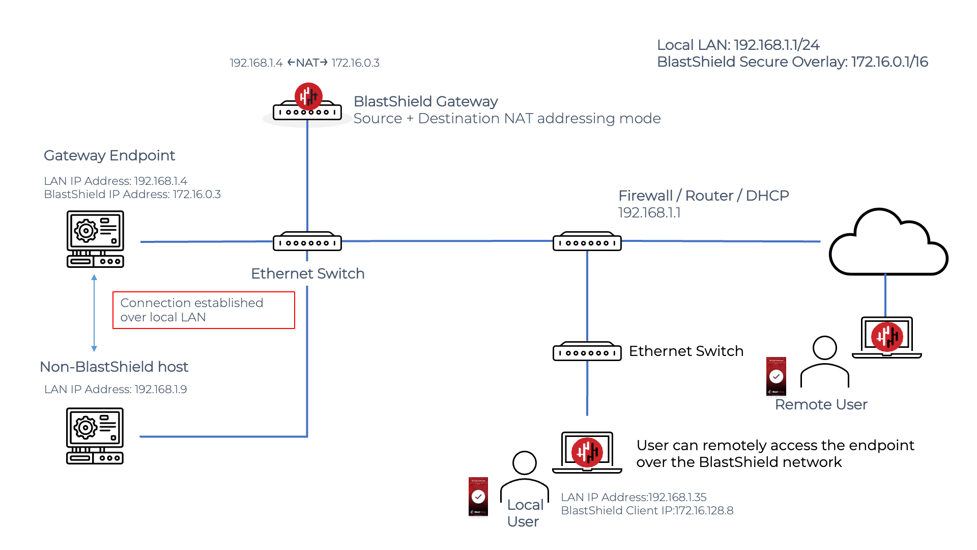
A remote BlastShield™ user will connect to an Endpoint on a passive Gateway as shown in the diagram below. The user must authenticate and connect to BlastShield™ before connecting and must have a policy to authorize connectivity to the Endpoint. The user simply opens a connection to the BlastShield™ Endpoint IP address in the overlay network, which in this example is the 172.16.0.3 address. The Gateway peforms the NATing and packet forwarding automatically so it is invisible to the user.
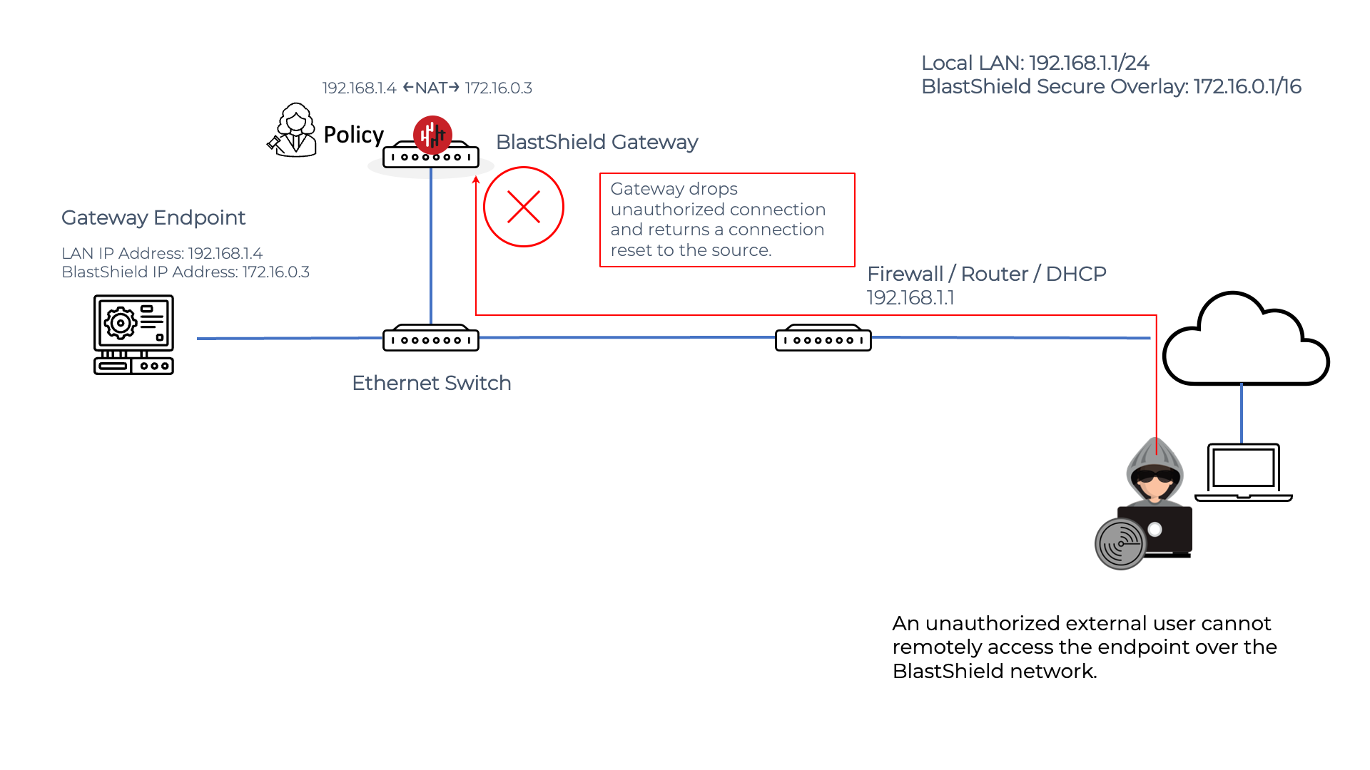
If an unauthorized external user attempts to initiate a connection to the BlastShield™ Endpoint, it will be blocked by the Gateway because it violates the zero-trust policy. The Gateway will drop the packets and return a connection reset to the source.
The destination NAT Passive Gateway
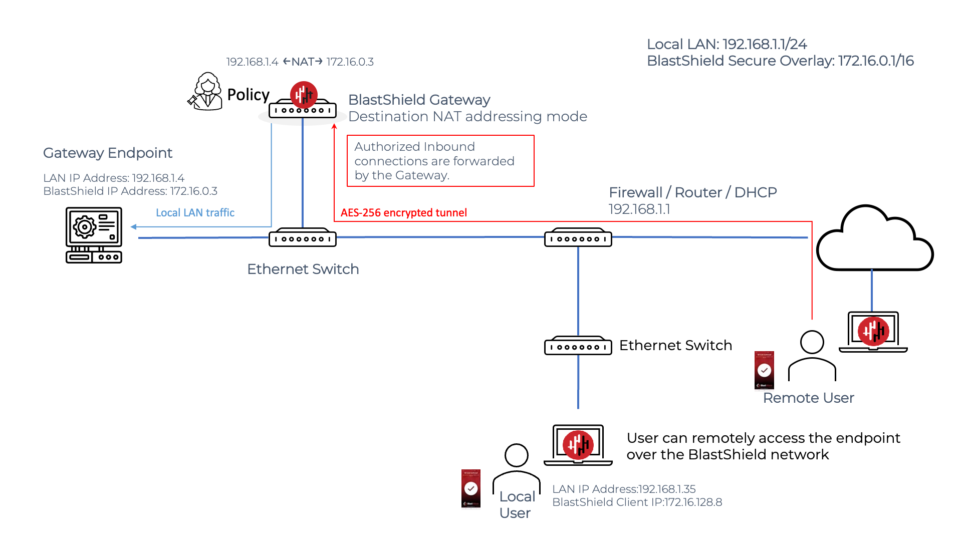
In the IP Address (Destination NAT) mode, the endpoint will see the source address as coming from the overlay IP prefix. This requires a routing change for the Endpoint to establish connections to Nodes in the BlastShield™ network overlay.
A remote BlastShield™ user will connect to an Endpoint on a passive Gateway as shown in the diagram below. The user must authenticate and connect to BlastShield™ before connecting and must have a policy to authorize connectivity to the Endpoint. The user simply opens a connection to the BlastShield™ Endpoint IP address in the overlay network, which in this example is the 172.16.0.3 address. The Gateway peforms the NATing and packet forwarding automatically so it is invisible to the user.
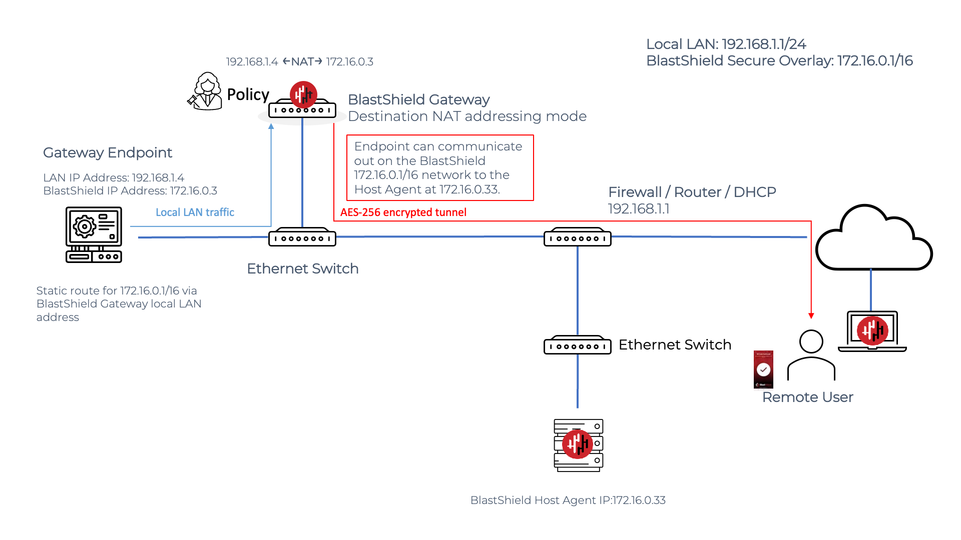
Endpoint connecting out over the BlastShield network on a Gateway using destination NAT
An Endpoint may connect out over the BlastShield™ network via a Gateway in destination NAT node. The Endpoint must have a static route added to it to specify the local LAN address of the BlastShield™ Gateway as the next hop address for the BlastShield™ network prefix.
Endpoint communication on a Passive Gateway
A Passive Gateway Endpoint may establish connections to non-BlastShield™ nodes in the local network, if required, using the local LAN IP address range. Connections which are established using the local LAN IP addressing range are not forwarded via the Gateway and so will function as normal, whereas connections addressed via the BlastShield™ overlay IP address range are forwarded via the Gateway according to the configured policy. This allows the Passive Gateway to be deployed for secure remote access, without affecting operation of existing nodes in the LAN. In private cloud environments you may also enable the cloud provider's firewall rules to only allow communications which are brokered via the Gateway.