NAT Gateway Installation on x86 hardware
The NAT Gateway type is used for the following use cases.
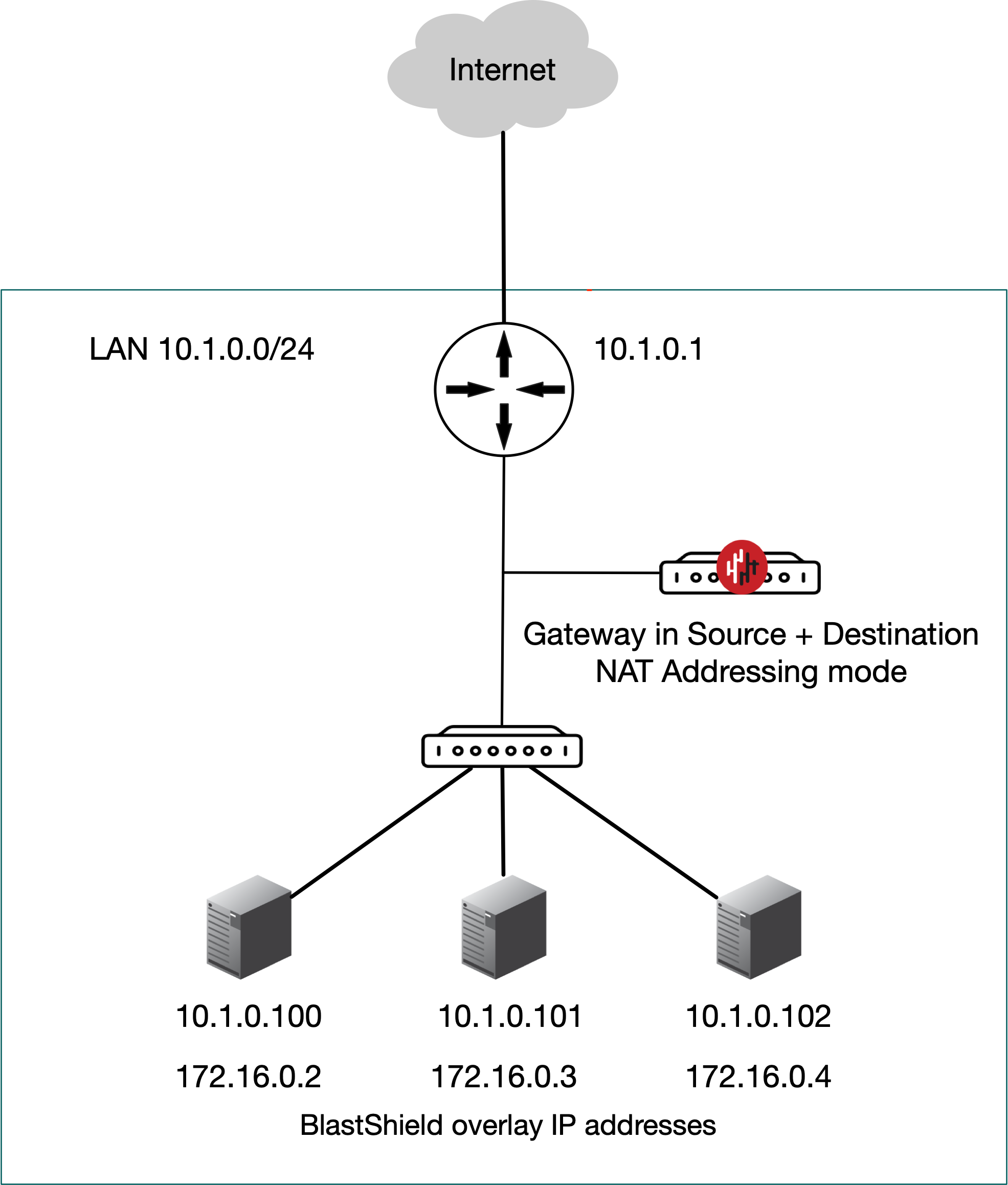
Passive Gateway (Source + Destination NAT addressing mode).
The Gateway is deployed passively to provide secure remote access to endpoints. It is installed out of line of the network path, so that it has no impact on the traffic between endpoints on the local network and requires no changes to the endpoints. All connections are encrypted end-to-end and micro-segmentation of users and endpoints with zero-trust policy is supported. The endpoints are able to communicate freely on their local LAN whilst at the same time secure remote access for users over the BlastShield™ network to these endpoints is managed by the Gateway. Endpoints will not be able to initiate connections out over the BlastShield™ network overlay because there is no route to the overlay network (if this is required, then use 'Destination NAT' mode).
A passive Gateway is configured by setting the Gateway addressing mode to IP Address (Source+Destination NAT). and it can be installed on hardware with a single NIC.
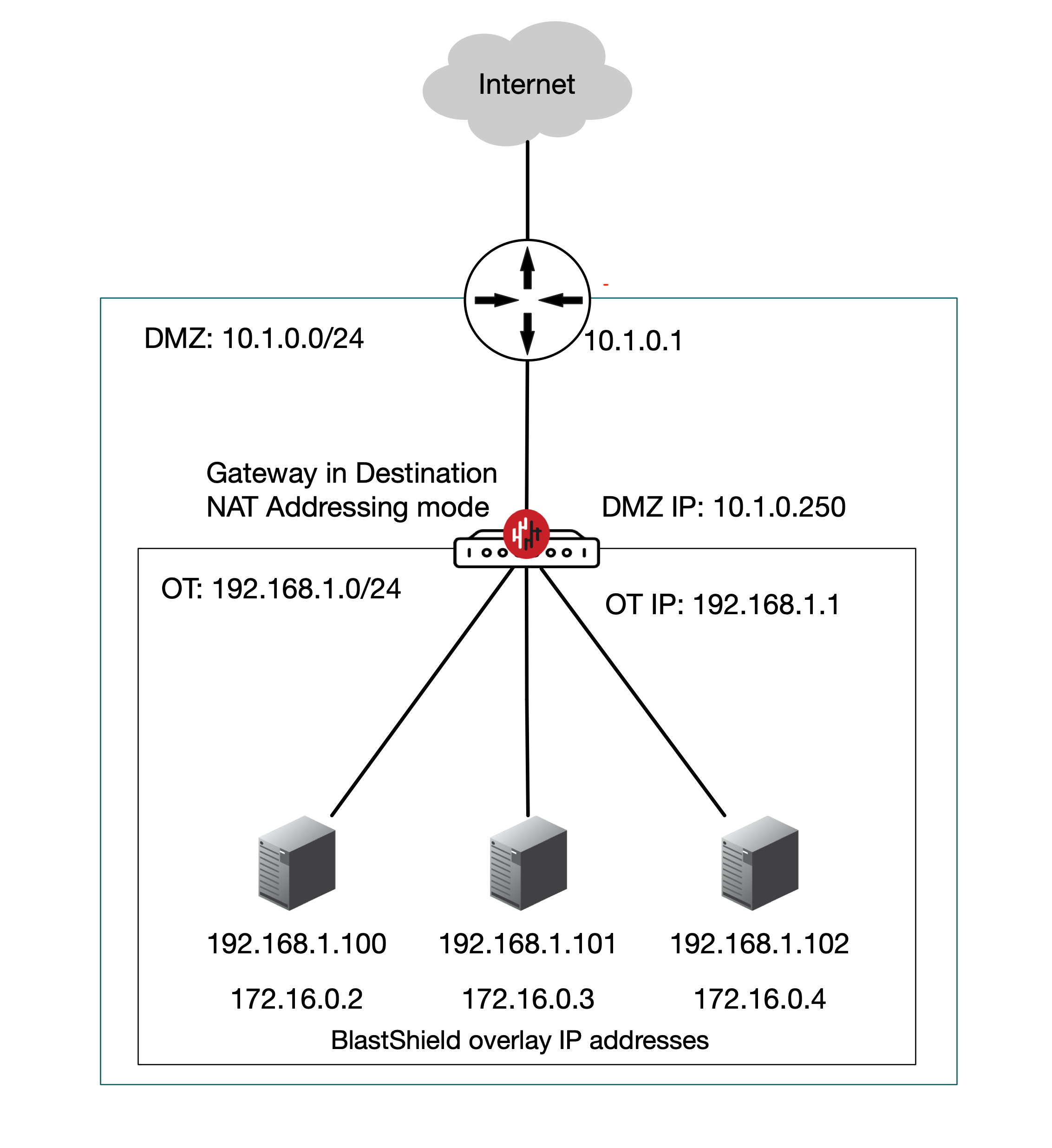
Inline Gateway as a router replacement (Destination NAT addressing mode).
In this scenario the BlastShield™ Gateway replaces the router between the OT and DMZ networks and performs all the routing between the subnets as well as providing secure remote access with microsegmentation of users and endpoints. The Gateway is located inline in the network path and provides isolation at the network layer, providing a virtual-air gap to protected endpoints so they appear invisible and isolated to unauthorized users. The endpoints are able to communicate freely on their local LAN.
Endpoints will be able to initiate connections out over the BlastShield™ network, provided the endpoints have a route added to the BlastShield™ overlay via the Gateway local LAN address.
An Active Gateway as a router replacement is configured by setting the Gateway addressing mode to IP Address (Destination NAT) and it can be installed on hardware with two or more NICs.
The Gateway addressing mode is set during the Gateway installation.
Install and provision the Gateway.
Create endpoints on the Gateway for the protected devices.
Configure an access policy and microsegmentation.
Prerequisites
Please be aware of the following requirements before you start:
You will require read / write access to your BlastShield™ Orchestrator.
Download the Gateway firmware. You can download it from here.
You will require a USB flash drive to boot your hardware from, and a monitor and keyboard to connect to your server during the installation process.
By default, the Gateway expects to receive an IP address from the network via DHCP for its public side interface. Manual assignment is also supported during the installation process.
You must have a suitable x86 hardware platform to install the Gateway software onto. Refer to the table of x86 Gateway hardware requirements for the minimum specifications.
x86 Gateway hardware requirements
Parameter | Value |
|---|---|
CPU | Minimum Intel Atom with AES-NI support or Intel Celeron with AES-NI support. Note that more powerful CPUs with AES-NI support such as Core i3 or Xeon are also supported. |
RAM | Minimum 4GB |
HDD/SSD | Minimum 8GB |
NICs | Two NICs required. Most NICs made by Intel, Broadcom and Mellanox are supported. |
Note: a USB interface is required to connect the boot media.
You can either provision and register the Gateway directly from the Orchestrator UI if your workstation has port 80 access to the Gateway, or you can provision the Gateway using the .BSI file if you do not have port 80 access to the Gateway from your workstation.
Use this method if you have port 80 access to the Gateway from your workstation.
Download the Gateway firmware and flash it to a USB.
Install the Gateway firmware on the x86 platform.
Provision the Gateway from the Orchestrator.
Download the Gateway firmware here.
Unzip the Installer Package (Do NOT run the Installer file).
Write the Installer Image to a USB drive using any available image writer
Note: there are several free utilities available for writing images to USB drives. We recommend the balenaEtcher software, but you can use any utility.
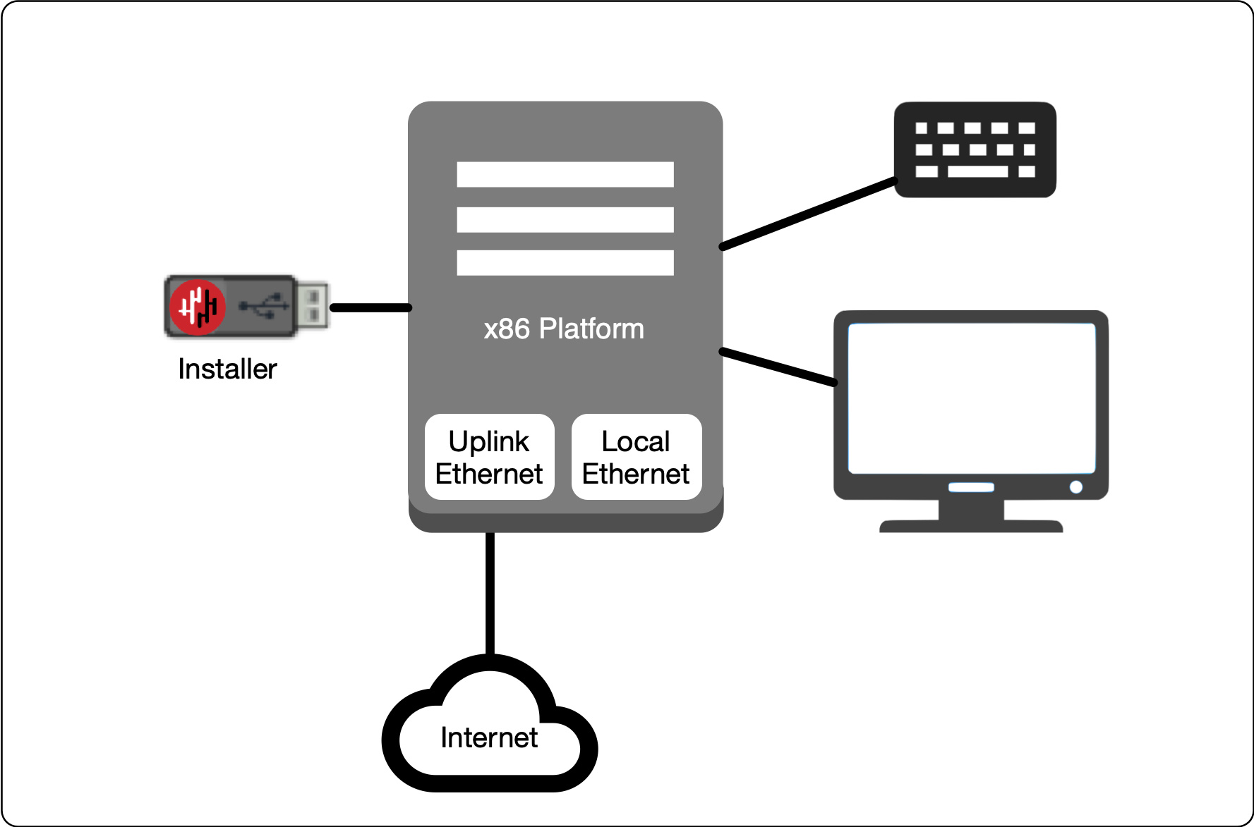
In this step you will be booting the x86 platform from the USB image created in the previous step.
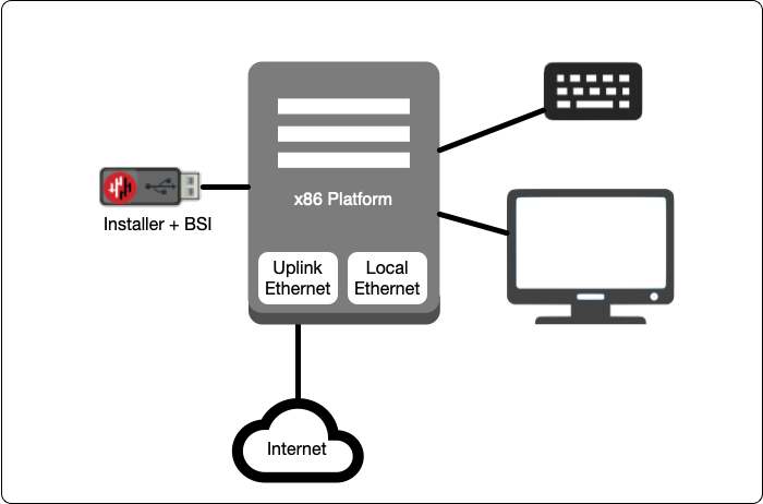
Connect your x86 platform as shown here, or use a serial console if you prefer.
 |
Watch the following video or read the steps below to learn how to boot the x86 platform from the USB image.
Making sure the x86 server is connected as shown above, power it on and exit the boot sequence using the break key that applies to your hardware, then select the boot setup menu.
Re-boot your server from the USB image, once the image boots you will begin the setup process.
Select the uplink (network) interface for the Gateway from the displayed list.
Select the address configuration (DHCP / manual configuration).
Wait for the Gateway network interface to come up.
You will see an alert prompting that there is no .BSI file on the USB and the Gateway will have to be provisioned post-install. Click OK.
Select the endpoint interface(s) from the displayed list. You may select more than one endpoint interface, depending on your hardware.
Use the up / down arrow keys to find each endpoint interface you want.
Press the space-bar to select an interface. An asterisk will appear next to the selected interface.
Press enter to confirm the selected interface(s).
Select the target device (hard drive).
Confirm that all data will be erased and the image will be installed on the server
When the installation is complete you will be prompted to remove the USB media. at this point, and the server will re-boot. You can disconnect the monitor and keyboard from the Gateway hardware now.
Remove the USB.
Click on OK
The Gateway will gracefully restart.
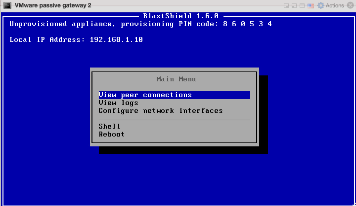
When the Gateway has restarted, the appliance provisioning menu will be displayed on the console. The Gateway is now ready to be provisioned from the Orchestrator.
This section explains how to provision an x86 Gateway directly from the Orchestrator UI without the need for a .BSI file. Do this after you have installed the Gateway firmware on the x86 hardware.
Important
Before you start, you must have already installed the Gateway image on your x86 hardware. You will need the Gateway IP address and provisioning PIN code which is displayed on the Gateway console menu as shown below.
|
Note the Gateway IP address and provisioning PIN code from the Gateway console menu.
To learn how to do this watch the following video or read the steps below. You will need the IP address and provisioning PIN code which is displayed on the Gateway console menu at the completion of the firmware installation (shown on the right hand side of the screen in this video). This method requires port 80 access to the Gateway from your workstation.
From the Orchestrator, select "Gateways" from the left Menu.
Select "Add New Gateway" from the Gateway List.
Enter a Name for the new Gateway.
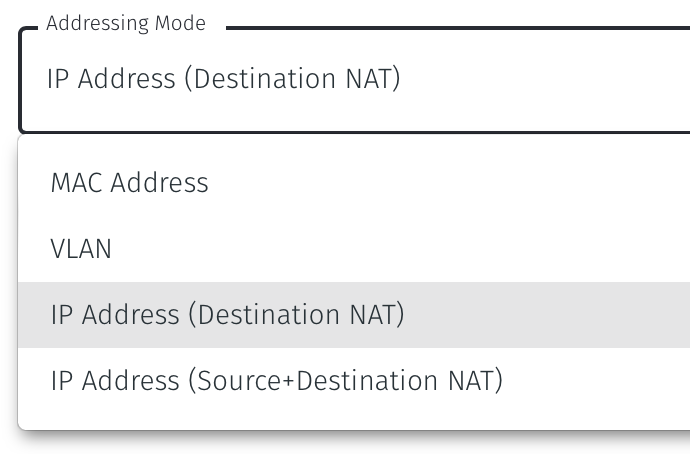
Set the Addressing Mode for the Gateway. The NAT Gateway may be configured with the addressing mode set to IP Address (Destination NAT) or IP Address (source+destination NAT), depending on your use case. You can choose from the options presented below.
Tip
For a inline router replacement Gateway choose IP Address (Destination NAT).
For a passive Gateway, choose IP Address (source+destination NAT),
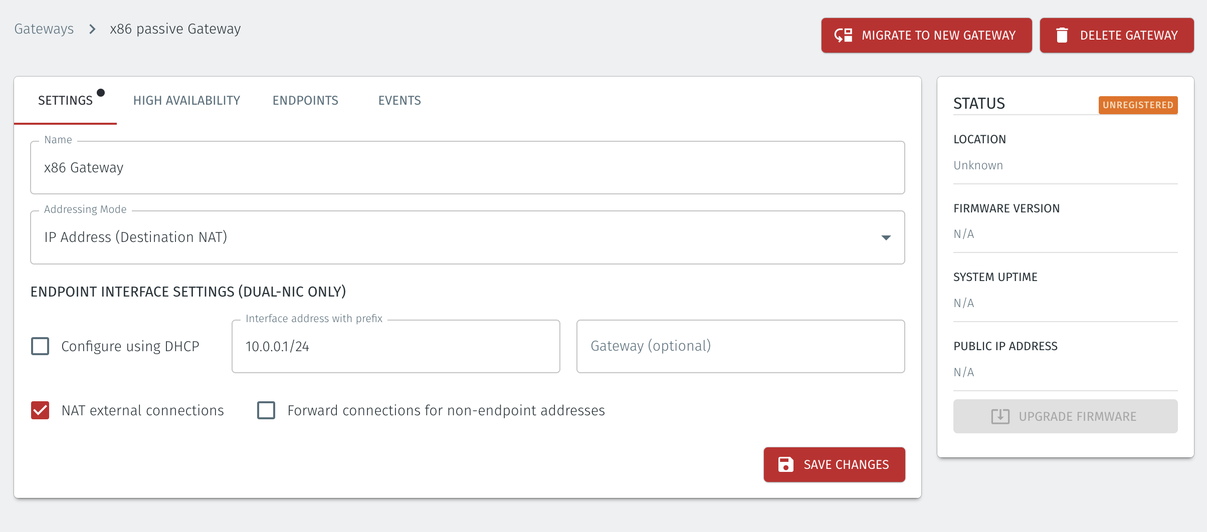
IP Address (Destination NAT) Addressing Mode
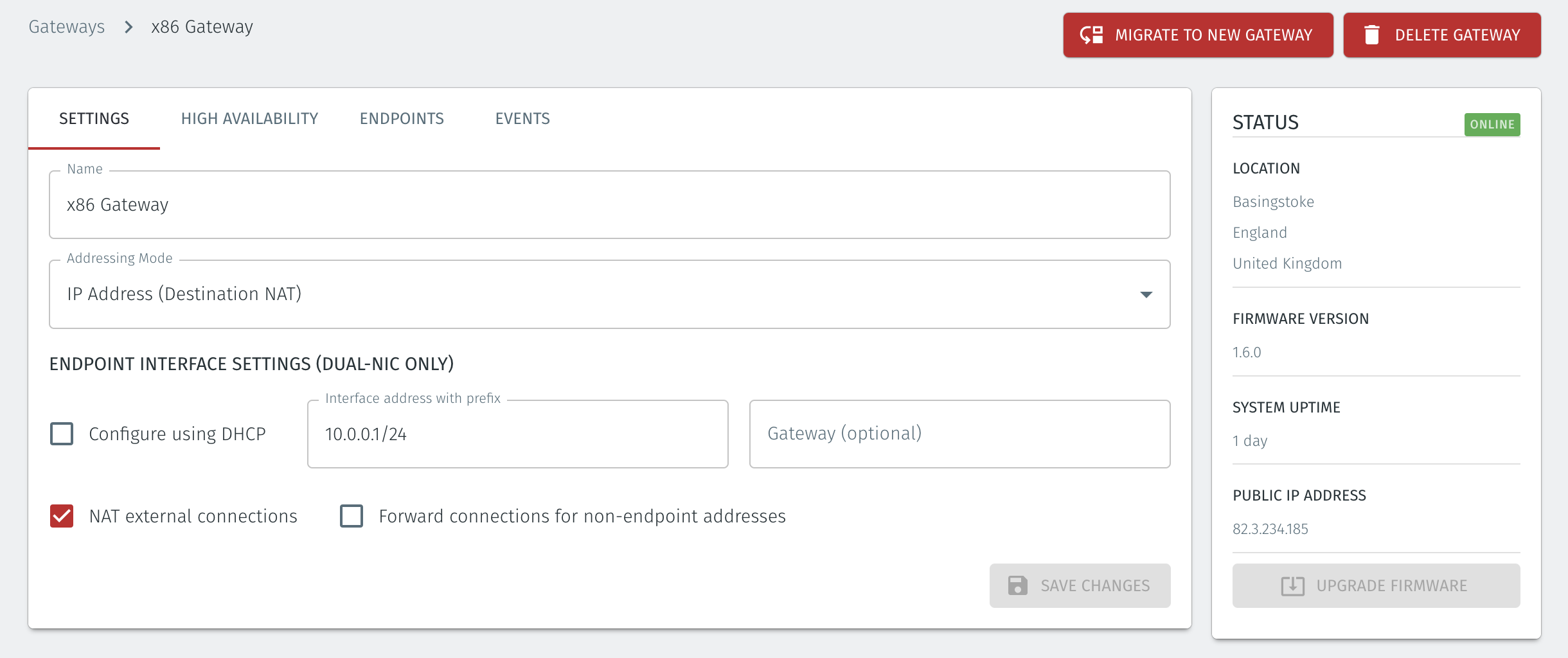
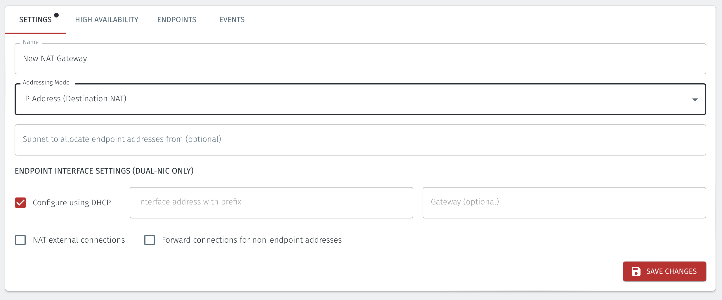
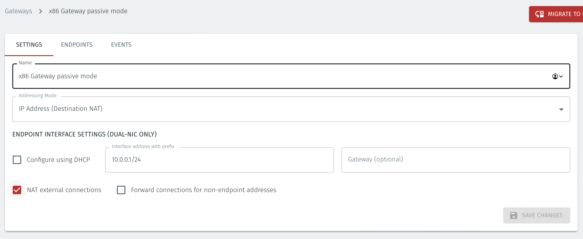
Set IP Address (Destination NAT) as the Addressing Mode.
If you are using the Gateway in a single NIC configuration, leave the Endpoint Interface Settings as default.
If you are using the Gateway as a router in a dual NIC configuration, then configure the Endpoint Interface Settings:
If you want the endpoint interface to get it's IP address via DHCP, then leave the configure using DHCP box checked.
If you want to manually set the endpoint interface IP address , then un-check the configure using DHCP box
Set the Interface address with prefix field to the same IP address as the router which the Gateway is replacing. Use CIDR format.
If you will be onboarding endpoints which are not within the subnet you specified with the interface address above, then enter the IP address of the gateway required to reach the endpoints in the Gateway (optional) field.
If you do not have a route on your internet router to the protected endpoint network, then enable NAT external connections by checking the box.
To enable the Gateway to forward non-endpoint connections from the protected network to the public side of the Gateway, check the Forward connections for non-endpoint addresses box. This will allow devices which are situated on the protected network side of the Gateway, which are not provisioned as endpoints on the Gateway, to forward traffic out through the Gateway.
IP Address (source+destination NAT) Addressing Mode
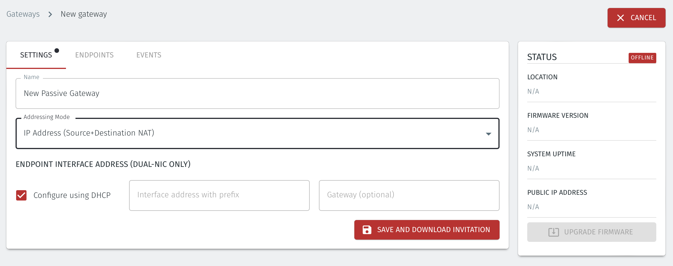
Set IP Address (Source+Destination NAT) as the Addressing Mode.
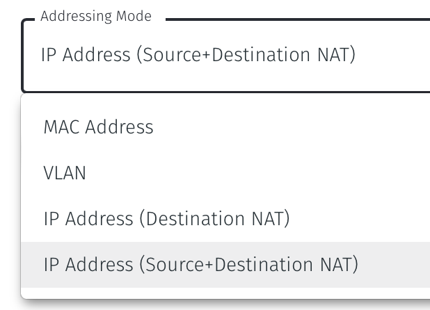
Once you have selected the addressing mode, the Gateway configuration window will update as shown below.
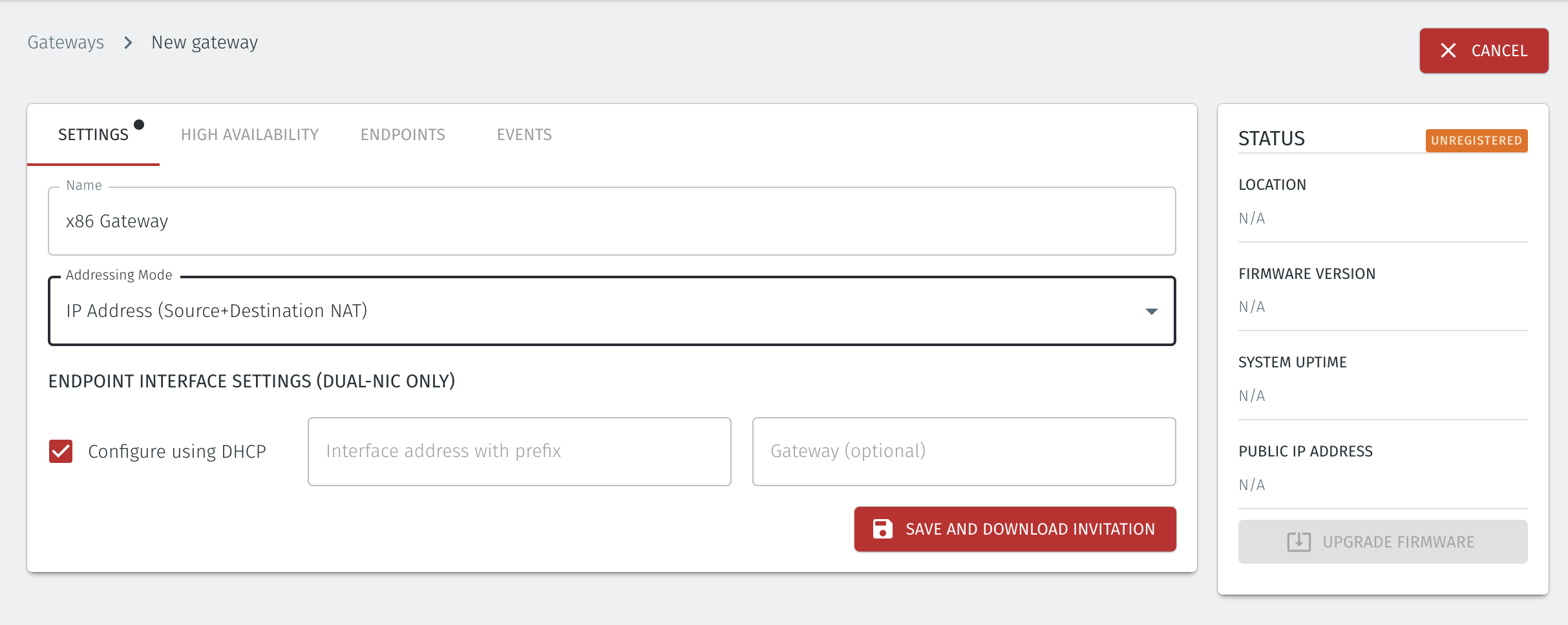
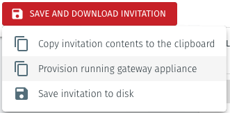
Select Save and Download Invitation.
Select the option Provision running gateway appliance to start the Gateway provisioning process.
The Provision Gateway window will open. Use the provisioning PIN code and Local IP Address that was displayed on the console menu at the end of the firmware installation process.
IP Address of Gateway: enter the IP address of the Gateway that is displayed in the Gateway console menu.
Provisioning PIN code: enter the provisioning PIN code that is displayed in the Gateway console menu.
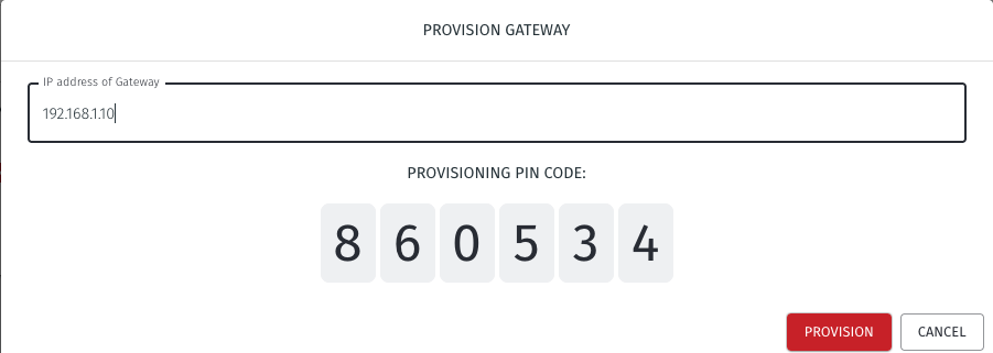
Click the Provision button to continue.
When the Gateway provisioning has completed, the Registration successful message will be displayed.
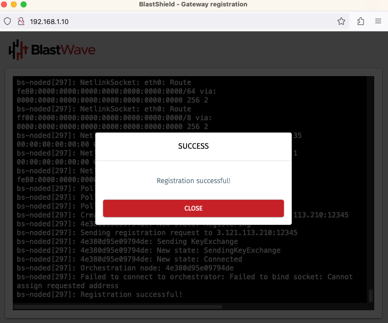
The Gateway status in the Orchestrator will show Online.
Use this method if you do not have port 80 access to the Gateway from your workstation.
Create a new Active Gateway in the Orchestrator and download the .BSI file.
Download the Gateway firmware and flash it to a USB. Copy the .BSI file to the USB.
Install the Gateway firmware on the x86 platform using the USB.
The NAT Gateway may be configured with the addressing mode set to destination NAT or source+destination NAT, depending on your use case. You can choose from the options below to learn how to create the Gateway.
Tip
For an inline router replacement Gateway, choose IP Address (destination NAT).
For a passive Gateway, choose IP Address (source+destination NAT).
From the Orchestrator, select "Gateways" from the left Menu.
Select Add New Gateway from the Gateway List.
Enter a Name for the new Gateway.
Set the Addressing Mode:
To use Source+Destination NAT addressing mode for endpoints on the Passive Gateway, chose IP Address (Destination NAT) as the Addressing Mode.
Once you have selected the addressing mode, the Gateway configuration window will update as shown below.
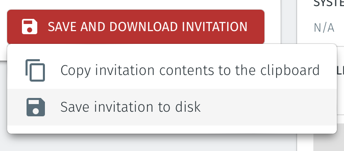
Select Save and Download Invitation.
Select the option Save Invitation to disk to download the invitation file to your local computer. You will need this file later when you install the Gateway.
From the Orchestrator, select "Gateways" from the left Menu.
Select Add New Gateway from the Gateway List.
Enter a Name for the new Gateway.
Set the Addressing Mode:
To use Destination NAT addressing mode for endpoints on the Passive Gateway, chose IP Address (Destination NAT) as the Addressing Mode.
Once you have selected the addressing mode, the Gateway configuration window will update as shown below.
If you are using the Gateway in a single NIC configuration, leave the Endpoint Interface Settings as default.
If you are using the Gateway as a router in a dual NIC configuration, then configure the Endpoint Interface Settings:
Set the Interface address with prefix field to the same IP address as the router which the Gateway is replacing. Use CIDR format.
If you will be onboarding endpoints which are not within the subnet you specified with the interface address above, then enter the IP address of the gateway required to reach the endpoints in the Gateway (optional) field.
If you do not have a route on your internet router to the protected endpoint network, then enable NAT external connections by checking the box.
To enable the Gateway to forward non-endpoint connections from the protected network to the public side of the Gateway, check the Forward connections for non-endpoint addresses box. This will allow devices which are situated on the protected network side of the Gateway, which are not provisioned as endpoints on the Gateway, to forward traffic out.
Select Save and Download Invitation.
Select the option Save Invitation to disk to download the invitation file to your local computer. You will need this file later when you install the Gateway.
Download the Gateway firmware here.
Unzip the Installer Package (Do NOT run the Installer file).
Write the Installer Image to a USB drive using any available image writer
Note: there are several free utilities available for writing images to USB drives. We recommend the balenaEtcher software, but you can use any utility.
Once you have written the image to USB, copy the invitation (.bsi) file in the root folder of this image on the USB.
In this step you will be booting the x86 platform from the USB image created in the previous step.
Connect your x86 platform as shown here or use a serial console if you prefer.
Please watch the following video or read the steps below to learn how to boot the x86 platform from the USB image.
Making sure the x86 server is connected as shown above, power it on and exit the boot sequence using the break key that applies to your hardware, then select the boot setup menu.
Re-boot your server from the USB image, once the image boots you will begin the setup process.
Select the uplink (network) interface for the Gateway from the displayed list.
Select the address configuration (DHCP / manual configuration).
Wait for the Gateway network interface to come up.
Select the endpoint interface(s) from the displayed list. You may select more than one endpoint interface, depending on your hardware.
Use the up / down arrow keys to find each endpoint interface you want.
Press the space-bar to select an interface. An asterisk will appear next to the target interface.
Press enter to confirm the selected interface(s).
Select the invitation (.bsi) file.
Select the target device (hard drive).
Confirm that all data will be erased and the image will be installed on the server
When the installation is complete you will be prompted to remove the USB media. at this point, and the server will re-boot.
Remove the USB.
Click on OK
The Gateway will gracefully restart.
Go to your Orchestrator, and verify the Gateway status is now Online.
For each of the devices that you want to securely connect to the BlastShield™ Gateway, you must create a corresponding endpoint for it on the Gateway. To learn how to do this, please read the following procedure.
In the Orchestrator, select the Gateway which you want to add the endpoints to, and then click on the endpoints tab.
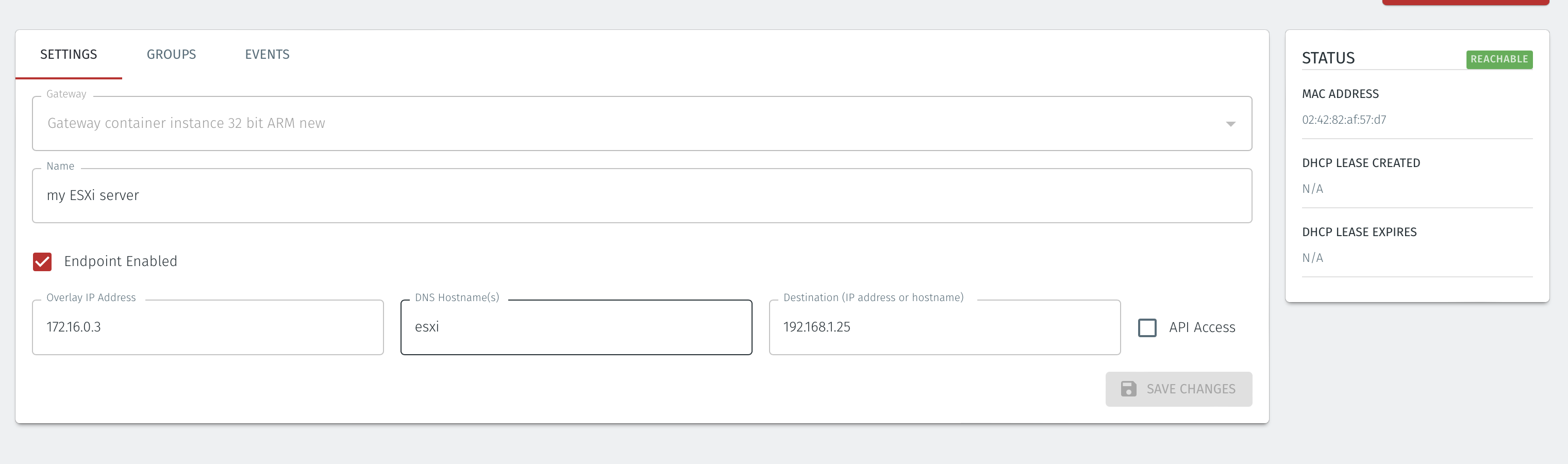
Click the 'Add New Endpoint' button and click on the 'Endpoint Enabled' button.
Enter a name for the endpoint in the Name field.
In the DNS Hostname field, enter a hostname for the BlastShield Network.
In the Destination field, enter the devices private IPv4 LAN address or hostname.
Click on 'Save Changes'.
The status of the endpoint will show as 'Online'.
In the Orchestrator, select the Gateway which you want to add the endpoints to, and then click on the endpoints tab.
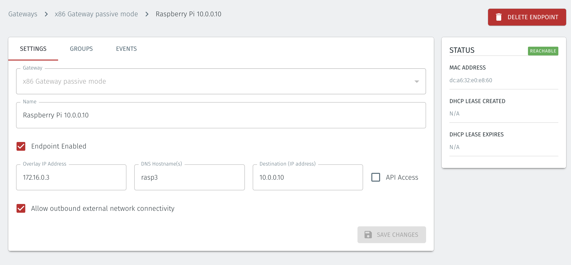
Click the 'Add New Endpoint' button and click on the 'Endpoint Enabled' button.
Enter a name for the endpoint in the Name field.
In the DNS Hostname field, enter a hostname for the BlastShield Network.
In the Destination field, enter the devices private IPv4 LAN address or hostname.
For a Gateway using Destination NAT addressing mode, If you want the endpoint to be able to communicate out through the Gateway (e.g. for transferring log files or making software updates) then check the box marked Allow outbound external network connectivity.
Click on 'Save Changes'.
The status of the endpoint will show as 'Online'.
For endpoints on Gateways which use destination NAT addressing mode only, modify the endpoint's route table so that the endpoint may connect out over the BlastShield™ network. If you are using a Gateway which is set to Source + Destination NAT you can skip this step.
In the endpoint host, add a route to the BlastShield™ overlay network via the Gateway local LAN address.
You can verify the BlastShield™ overlay network prefix in the network settings/Overlay Subnet settings in the Orchestrator. The default overlay network prefix is 172.16.0.0/16.
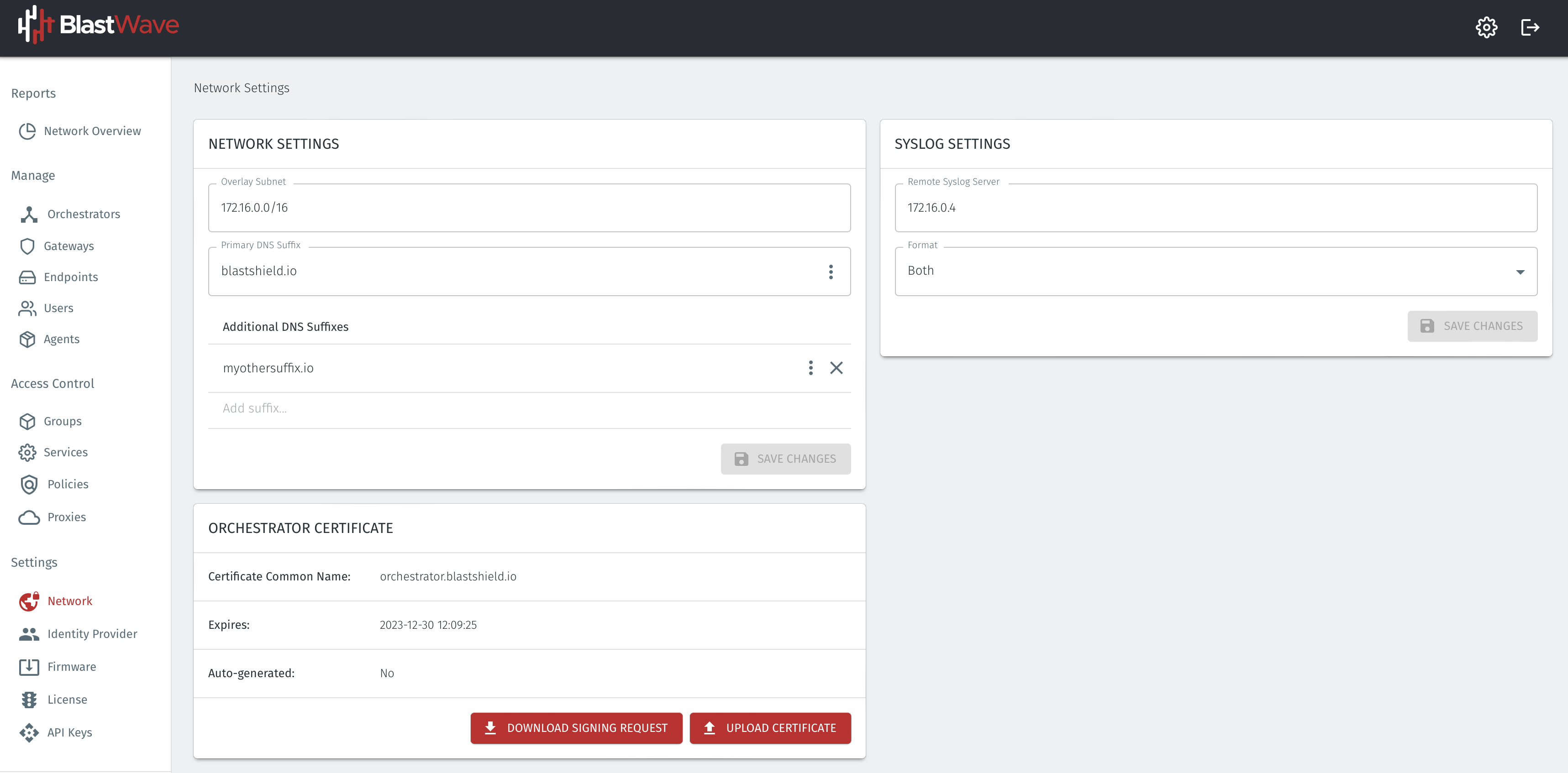
You can find the Gateway local LAN address in the Gateway settings, in the Interface address with prefix setting.
An example of the route to add in the endpoint host for this scenario would be
ip route add 172.16.0.0/16 via 10.0.0.1 [dev interface]
About Groups
Groups allow you to micro-segment users and endpoints. A group is a logical collection of endpoints and/or users that are grouped together. Groups are connected via policies, which form the foundation for BlastShield access control and segmentation management.
Any combination of endpoints and/or users can be grouped together.
There is no limit to the number of endpoints and/or users that can be in a group.
Endpoints and users can be in one or multiple groups simultaneously.
Groups are linked together via policies to provide access between endpoints.
By default, endpoints/users cannot access or have visibility to other endpoints/users unless they are granted access via a policy
About Policies
A policy defines how groups can interact. Groups are connected via policies, which form the foundation for BlastShield access control and segmentation management.
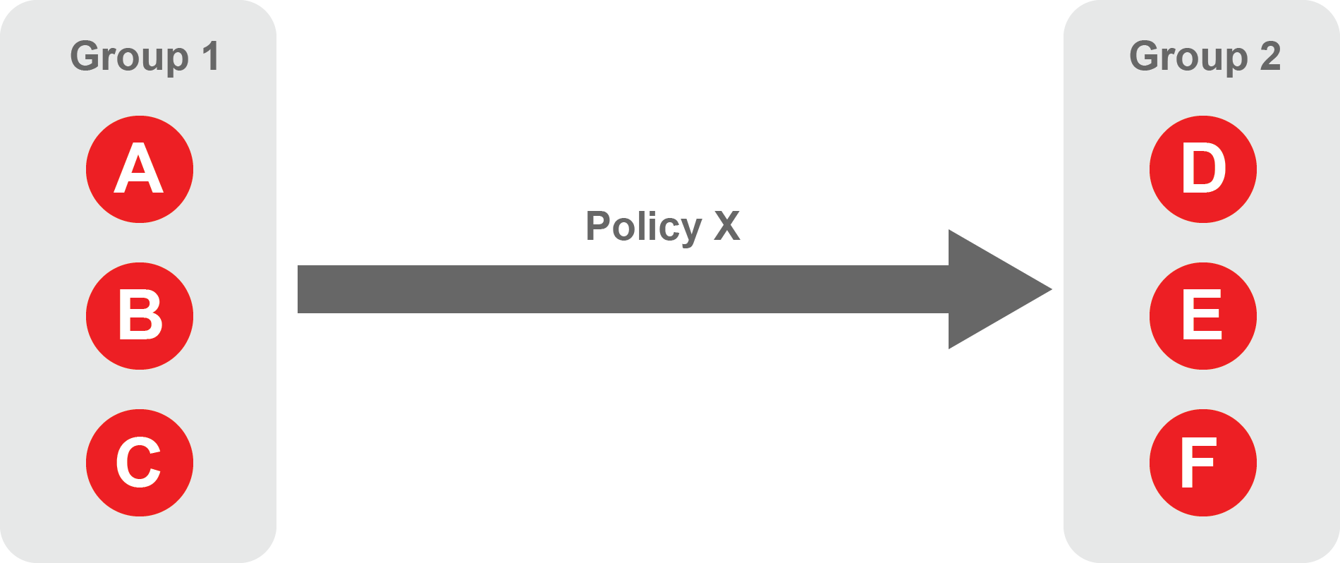
Each policy will have two sets of groups - "From" and "To".
The "From" set is one or more source groups.
The "To" set is one or more destination groups.
There is no limit to the number of groups in a given policy.
"From" Groups will have access to "To" Groups within the policy.
"To" Groups will not have access to "From" Groups within the policy.
Groups can be in one or multiple policies simultaneously.
 |
Create Groups
From the Orchestrator, select "Groups" from the left menu.
Select "Add New Group" from the Group List.
Enter a name for the new Group.
To add members to the new group, click the "Add Members" button.
If you adding users to the group then select the desired Users which you want to be associated with the Group from the "Users" box.
If you are adding Agents to the group then select the desired Agents which you want to be associated with the Group from the "Agents" box.
If you are adding Gateway Endpoints then select the desired Endpoints from the "Endpoints" box.
Alternatively, you can leave the members list empty and add/modify new members later.
Click "Add Members" to save the members.
Click "Save" to save the new group.
Repeat, if required, to ensure you have one group for your endpoints and one group for your users, which is the minimum you will need in order to define the access policy.
Please refer to the following video, which is an example of creating one group for your users and one group for Host Agents.
Create a Policy to link your Groups
Note
Users and Agents must be a member of a group for them to be used in a policy.
Select "Policies" from the left menu.
Select "Add New Policy" from the Policy List.
Enter a name for the new Policy.
Select desired "From" Groups to be associated with the new Policy.
Select desired "To" Groups to be associated with the new Policy.
Save the new Policy.
Policies are directional, so that you can control the direction in which connections may be initiated. Typically for remote access use-cases your policy would be from the "user group" to the "server group" so that users may start connections to the servers, but servers cannot start connections to users. You can create bi-directional permissions by using two policies.
The following video shows an example of creating an access Policy between a group of remote workers and a group of servers. The policy gives the remote workers authorisation to access the server group.